SHIFT PADDLE SWITCH INSPECTION
PROCEDURE
-
INSPECT TRANSMISSION SHIFT SWITCH ASSEMBLY
-
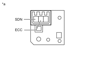
*a Component without harness connected
(Transmission Shift Switch Assembly LH)
Measure the resistance according to the value(s) in the table below.
Standard Resistance Transmission Shift Switch Assembly LH: Tester Connection Switch Condition Specified Condition SDN - ECC "-" continuously pulled Below 2.5 Ω Released 1 MΩ or higher If the resistance values are not as specified, replace the transmission shift switch assembly LH.
-
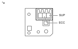
*a Component without harness connected
(Transmission Shift Switch Assembly RH)
Measure the resistance according to the value(s) in the table below.
Standard Resistance Transmission Shift Switch Assembly RH: Tester Connection Switch Condition Specified Condition SUP - ECC "+" continuously pulled Below 2.5 Ω Released 1 MΩ or higher If the resistance values are not as specified, replace the transmission shift switch assembly RH.
-
-
INSPECT NO.1 SWITCH WIRE
-
Disconnect the No. 1 switch wire connector from the steering pad switch assembly.
-
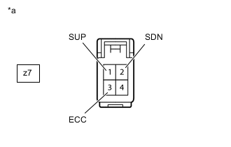
*a No. 1 switch wire
(to Steering Pad Switch Assembly)
Measure the resistance according to the value(s) in the table below.
Standard Resistance Tester Connection Switch Condition Specified Condition z7-2 (SDN) - z7-3 (ECC) "-" shift paddle operated and held
(down-shift)
Below 2.5 Ω "-" shift paddle not operated
(down-shift)
1 MΩ or higher z7-1 (SUP) - z7-3 (ECC) "+" shift paddle operated and held
(up-shift)
Below 2.5 Ω "+" shift paddle not operated
(up-shift)
1 MΩ or higher If the resistance value is not as specified, replace the No. 1 switch wire.
-