AIR CONDITIONING SYSTEM(for Manual Air Conditioning System) SYSTEM DESCRIPTION
GENERAL
The air conditioning system has the following controls.
Control
Outline
Manual Control
Damper positions and blower speed operate automatically according to the operation of switches such as the temperature control switch, blower switch, mode control switch and inlet control switch.
Compressor Control
Through the calculation of the target evaporator temperature based on various sensor signals, the air conditioning amplifier optimally controls discharge capacity by regulating the opening extent of the compressor solenoid valve.
Diagnosis
A Diagnostic Trouble Code (DTC) is stored in memory when the air conditioning amplifier assembly detects a problem with the air conditioning system.
MODE POSITION AND DAMPER OPERATION
Mode Position and Damper Operation.

*A
w/ PTC Heater
-
-
*1
Front Defroster
*2
Side Defroster
*3
Fresh Air
*4
Recirculated Air
*5
Blower Motor
*6
No. 1 Cooler Evaporator Sub-assembly
*7
Heater Radiator Unit
*8
Quick Heater Assembly
*9
Side Resistor
*10
Center Resistor
*11
Upper Resistor
*12
Rear Footwell Resistor Duct
*13
Footwell Resistor
-
-
Table 1. Functions of Main Dampers Control Damper
Operation Position
Damper Position
Operation
Air Inlet Control Damper
FRESH
A
Allows fresh air to enter.
RECIRCULATION
B
Causes internal air to recirculate.
Air Mix Control Damper
MAX COLD to MAX HOT Temperature Setting
C - D - E
Varies the mixture ratio of warm air and cool air in order to regulate the temperature continuously between hot and cold.
Air Outlet Control Damper
DEF

H, K
Air blows out of the center defroster, side defrosters and side registers.
FOOT / DEF

H, J
Air blows out of the front footwell register ducts, side registers and center defroster.
FOOT

H, I
Air blows out of the side registers and front footwell register ducts. In addition, air blows out slightly from the center defroster and side defrosters.
BI-LEVEL

F, I
Air blows out of the front footwell register ducts, front center registers and side registers.
FACE

F, K
Air blows out of the front center registers and side registers.
AIR OUTLETS AND AIRFLOW VOLUME
Air Outlets and Airflow Volume.
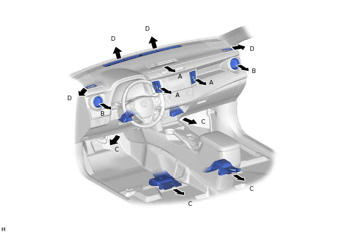
Indication
Mode
A
B
C
D
Center, Upper
Side
Lower
Defroster
FACE


B/L

FOOT

F/D
DEF
The size of each circle ○ indicates the ratio of airflow volume.