CAN COMMUNICATION SYSTEM(w/o Central Gateway ECU) SYSTEM DIAGRAM
-
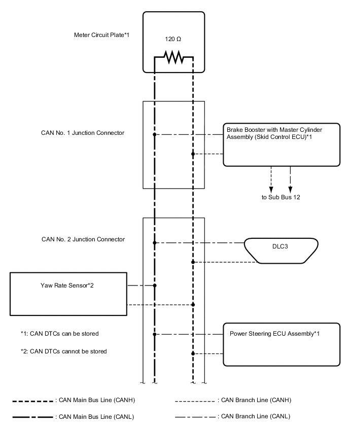
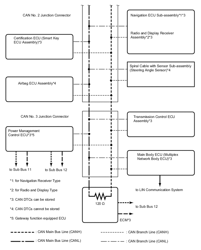
OVERALL CAN BUS DIAGRAM (for LHD)
-
Control system CAN is composed of 3 buses.
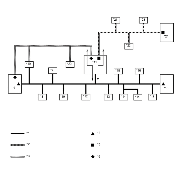
Text in Illustration *1 V Bus *2 Sub Bus 11 *3 Sub Bus 12 *4 V Bus Terminating Resistor *5 Sub Bus 11 Terminating Resistor *6 Sub Bus 12 Terminating Resistor *7 ECM
(for V Bus and Sub Bus 12)
*8 Main Body ECU (Multiplex Network Body ECU)
(for V Bus)
*9 DLC3
(for V Bus)
*10 Airbag ECU Assembly
(for V Bus)
*11 Power Management Control ECU
(Gateway Function Equipped ECU)
*12 Certification ECU (Smart Key ECU Assembly)
(for V Bus)
*13 Spiral Cable with Sensor Sub-assembly (Steering Angle Sensor)
(for V Bus)
*14
-
Navigation ECU Sub-assembly
-
Radio and Display Receiver Assembly
(for V Bus)
*15 Power Steering ECU Assembly
(for V Bus)
*16 Yaw Rate Sensor
(for V Bus)
*17 Transmission Control ECU Assembly
(for V Bus)
*18 Meter Circuit Plate
(for V Bus)
*19 Brake Booster with Master Cylinder Assembly (Skid Control ECU)
(for V Bus and Sub Bus 12)
*20 Air Conditioning Amplifier Assembly
(for Sub Bus 12)
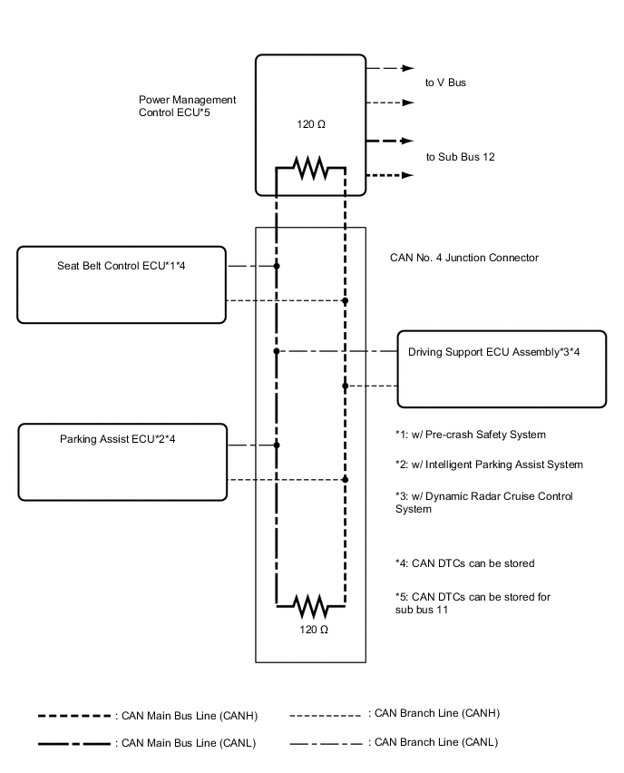
*21 Seat Belt Control ECU
(for Sub Bus 11)
*22 Parking Assist ECU
(for Sub Bus 11)
*23 Driving Support ECU Assembly
(for Sub Bus 11)
*24 CAN No. 4 Junction Connector
(for Sub Bus 11)
Tech Tips
-
The power management control ECU functions as a gateway between the V bus and sub bus 11, and the V bus and sub bus 12.
-
Refer to the following bus wiring diagrams for details.
-
-
-
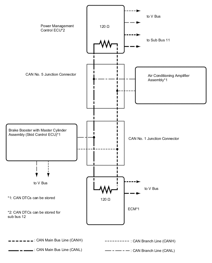
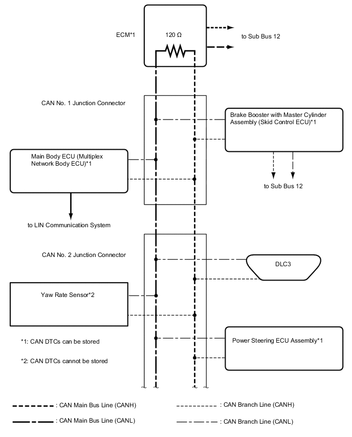
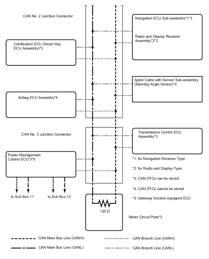
V BUS (for LHD)
Tech Tips
The CAN communication system connects to other networks via ECUs that function as a gateway Click here.
-
OVERALL CAN BUS DIAGRAM (for RHD)
-
Control system CAN is composed of 3 buses.
Text in Illustration *1 V Bus *2 Sub Bus 11 *3 Sub Bus 12 *4 V Bus Terminating Resistor *5 Sub Bus 11 Terminating Resistor *6 Sub Bus 12 Terminating Resistor *7 ECM
(for V Bus and Sub Bus 12)
*8 Main Body ECU (Multiplex Network Body ECU)
(for V Bus)
*9 DLC3
(for V Bus)
*10 Airbag ECU Assembly
(for V Bus)
*11 Power Management Control ECU
(Gateway Function Equipped ECU)
*12 Certification ECU (Smart Key ECU Assembly)
(for V Bus)
*13 Spiral Cable with Sensor Sub-assembly (Steering Angle Sensor)
(for V Bus)
*14
-
Navigation ECU Sub-assembly
-
Radio and Display Receiver Assembly
(for V Bus)
*15 Power Steering ECU Assembly
(for V Bus)
*16 Yaw Rate Sensor
(for V Bus)
*17 Transmission Control ECU Assembly
(for V Bus)
*18 Meter Circuit Plate
(for V Bus)
*19 Brake Booster with Master Cylinder Assembly (Skid Control ECU)
(for V Bus and Sub Bus 12)
*20 Air Conditioning Amplifier Assembly
(for Sub Bus 12)
*21 Seat Belt Control ECU
(for Sub Bus 11)
*22 Parking Assist ECU
(for Sub Bus 11)
*23 Driving Support ECU Assembly
(for Sub Bus 11)
*24 CAN No. 4 Junction Connector
(for Sub Bus 11)
Tech Tips
-
The power management control ECU functions as a gateway between the V bus and sub bus 11, and the V bus and sub bus 12.
-
Refer to the following bus wiring diagrams for details.
-
-
-
V BUS (for RHD)
Tech Tips
The CAN communication system connects to other networks via ECUs that function as a gateway Click here.
-
SUB BUS 11
-
SUB BUS 12