СИСТЕМА SFI Variable Resistor Circuit
DESCRIPTION
This resistor is used to change the air-fuel ratio of the air-fuel mixture.
The idle mixture is adjusted using this resistor.
Turning the idle mixture adjusting screw clockwise moves the contacts inside the resistor, raising the terminal VAF voltage. Conversely, turning the screw counterclockwise lowers the terminal VAF voltage.
When the terminal VAF voltage rises, the ECM increases the injection volume slightly, making the air-fuel mixture a little richer.
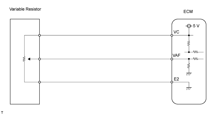
WIRING DIAGRAM
INSPECTION PROCEDURE
PROCEDURE
-
CHECK CO/HC
-
Warm up the engine to normal operating temperature.
-
Turn all accessories OFF.
-
Connect all vacuum lines properly.
-
Connect the tachometer.
-
Check ignition timing correctly.
-
Check idle speed correctly.
-
Check that the CO meter is properly calibrated.
-
Race the engine at 2,500 rpm about 2 minutes.
-
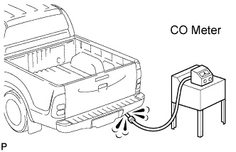
Insert a tester probe at least 40 cm (1.3 ft.) into the tailpipe.
-
Measure the concentration with 1 to 3 minutes after racing the engine to allow the concentration to stabilize.
Idle CO concentration 1 to 2%
OK 
CHECK FOR PROBLEM SYMPTOMS TABLE
NG 
-
-
ADJUST CO CONCENTRATION
-
Put the vehicle in the same condition as the previous step (CHECK CO/HC).
-
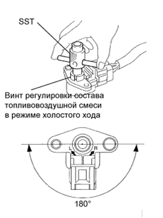
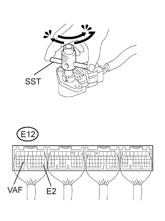
Using SST, adjust the idle mixture by turning the idle mixture adjusting screw in the variable resistor.
Result Result Proceed Concentration: 1.5 +- 0.5% B Change in CO concentration C No change in CO concentration A Tech Tips
-
Always check idle speed after turning the idle mixture adjusting screw. If it is incorrect, readjust idle speed.
-
The idle mixture adjusting screw can be turned within 180°. Do not turn this screw more than specified.
- SST
- 09243-00020
-
B
ADJUSTMENT COMPLETE
C
CHECK CO/HC
A
-
-
INSPECT VARIABLE RESISTOR
-
Measure the resistance according to the value(s) in the table below.
Resistance Tester Connection Specified Condition 1 - 2 3.5 to 6.5 Ω -
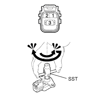
While fully turning the idle mixture adjusting screw clockwise and counterclockwise using SST, measure the resistance.
Resistance Tester Connection Specified Condition 2 - 3 Resistance changes from approximately 5 to 0 kΩ - SST
- 09243-00020
NG
REPLACE VARIABLE RESISTOR
OK
-
-
CHECK ECM (VAF VOLTAGE)
-
Turn the ignition switch ON.
-
While fully turning the idle mixture adjusting screw clockwise and counterclockwise slowly using SST, measure the voltage.
Standard voltage Tester Connection Specified Condition E12-25 (VAF) - E12-28 (E2) Voltage changes smoothly from 0 to approximately 5 V (does not change suddenly) - SST
- 09243-00020
OK
REPLACE ECM
NG
-
-
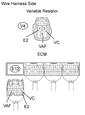
CHECK WIRE HARNESS (VARIABLE RESISTOR - ECM)
-
Disconnect the V4 variable resistor connector.
-
Disconnect the E12 ECM connector.
-
Measure the resistance of the wire harness side connectors.
Standard resistance Tester Connection Specified Condition V4-2 (VC) - E12-18 (VC) Below 1 Ω V4-3 (VAF) - E12-25 (VAF) Below 1 Ω V4-1 (E2) - E12-28 (E2) Below 1 Ω V4-2 (VC) or E12-18 (VC) - Body ground 10 kΩ or higher V4-3 (VAF) or E12-25 (VAF) - Body ground 10 kΩ or higher
NG
REPAIR OR REPLACE HARNESS AND CONNECTOR
OK 
REPLACE ECM
-