AUDIO AND VISUAL SYSTEM(w/ Multi-display) Sound Signal Circuit between Radio Receiver and Stereo Jack Adapter
| DTC Code | DTC Name |
|---|---|
| Sound Signal Circuit between Radio Receiver and Stereo Jack Adapter |
DESCRIPTION
The No. 1 stereo jack adapter assembly sends an external device sound signal to the radio receiver assembly through this circuit.
The sound signal that has been sent is amplified by the stereo component amplifier assembly or radio receiver assembly, and then is sent to the speakers.
If there is an open or short in the circuit, sound cannot be heard from the speakers even if there is no malfunction in the stereo component amplifier assembly, radio receiver assembly or speakers.
WIRING DIAGRAM
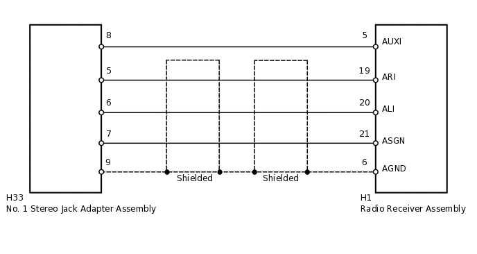
PROCEDURE
CHECK HARNESS AND CONNECTOR (NO. 1 STEREO JACK ADAPTER - RADIO RECEIVER)
Disconnect the H33 No. 1 stereo jack adapter assembly connector.
Disconnect the H1 radio receiver assembly connector.
Measure the resistance according to the value(s) in the table below.
Standard Resistance
Tester Connection
Condition
Specified Condition
H33-8 - H1-5 (AUXI)
Always
Below 1 Ω
H33-7 - H1-21 (ASGN)
Always
Below 1 Ω
H33-5 - H1-19 (ARI)
Always
Below 1 Ω
H33-6 - H1-20 (ALI)
Always
Below 1 Ω
H33-9 - H1-6 (AGND)
Always
Below 1 Ω
H33-8 - Body ground
Always
10 kΩ or higher
H33-7 - Body ground
Always
10 kΩ or higher
H33-5 - Body ground
Always
10 kΩ or higher
H33-6 - Body ground
Always
10 kΩ or higher
H33-9 - Body ground
Always
10 kΩ or higher
Result
Result
OK
NG
NG REPAIR OR REPLACE HARNESS OR CONNECTOR