STOP AND START SYSTEM(for 3ZR-FAE), Diagnostic DTC:P161D
| DTC Code | DTC Name |
|---|---|
| P161D | Starter Delay Circuit |
DESCRIPTION
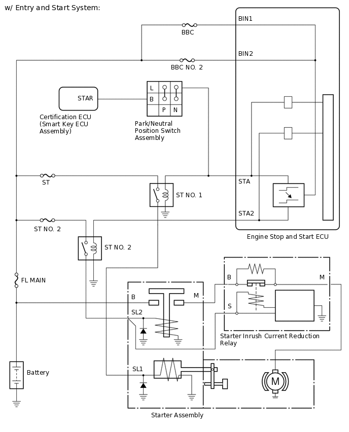
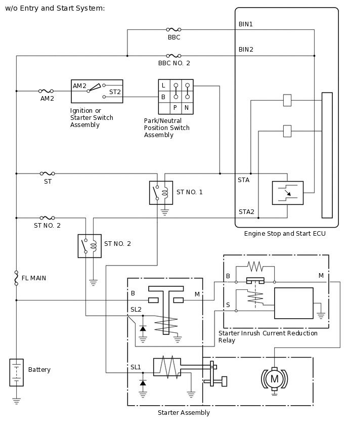
By using the starter delay circuit, the engine stop and start ECU can activate the ST NO. 2 relay (for starter motor operation) after activating the ST NO. 1 relay (for starter pinion operation) to operate the starter assembly.
By monitoring the condition of the ST NO. 1 relay (for starter pinion operation) and ST NO. 2 relay (for starter motor operation), the engine stop and start ECU detects if the transistor of the starter delay circuit is stuck. If the transistor of the starter delay circuit is stuck on, the engine stop and start ECU blinks the stop and start cancel indicator light and stores DTC P161D. If the transistor of the starter delay circuit is stuck on, the ST NO. 1 relay (for starter pinion operation) and ST NO. 2 relay (for starter motor operation) will be activated simultaneously.
DTC No. |
Detection Item |
DTC Detection Condition |
Trouble Area |
Warning Indicate |
Memory |
|---|---|---|---|---|---|
P161D |
Starter Delay Circuit |
Both of the following conditions are met (1 trip detection logic):
|
Engine stop and start ECU |
Blinks |
DTC stored |
CONFIRMATION DRIVING PATTERN
DTCs for the stop and start system are not cleared even if the malfunction has been repaired. After repairing the malfunction, be sure to clear the DTCs.
CONFIRMATION AFTER TROUBLESHOOTING
Tip:If the cable is disconnected from the negative (-) battery terminal, stop and start control is prohibited until refresh charge is completed. In this case, drive the vehicle approximately 5 to 60 minutes until refresh charge is completed and stop and start control operation is permitted.
Allow the engine to idle for 3 minutes after it is warmed up and check that the engine idle speed is within 50 rpm of the target idle speed.
Connect the GTS to the DLC3.
Turn the ignition switch to ON and turn the GTS on.
Clear the DTCs.
Powertrain > Stop and Start > Clear DTCs
Start the engine and warm it up.
Drive the vehicle at 7 km/h (4.3 mph) or more.
CAUTION:When performing Confirmation Driving Pattern, obey all speed limits and traffic laws.
Depress the brake pedal and stop the vehicle.
Keep the engine stopped by stop and start control. (Keep the shift lever in D.)
Release the brake pedal with the shift lever in D to start the engine.
Check that no DTCs are output.
Powertrain > Stop and Start > Trouble Codes
STOP AND START SYSTEM OPERATION CHECK
Tip:If the cable is disconnected from the negative (-) battery terminal, stop and start control is prohibited until refresh charge is completed. In this case, drive the vehicle approximately 5 to 60 minutes until refresh charge is completed and stop and start control operation is permitted.
Start the engine and warm it up.
Turn the air conditioning system off.
Drive the vehicle at 7 km/h (4.3 mph) or more.
CAUTION:When performing Confirmation Driving Pattern, obey all speed limits and traffic laws.
Depress the brake pedal and stop the vehicle.
Allow the engine to stop by stop and start control. (Keep the shift lever in D.)
Release the brake pedal with the shift lever in D to start the engine.
WIRING DIAGRAM
CAUTION / NOTICE / HINT
When replacing the engine stop and start ECU with a new one, make sure to download the previous status (number of starter operations) of the old engine stop and start ECU. After replacing the engine stop and start ECU, turn the ignition switch to ON and wait 20 seconds, then confirm that "OK" is displayed for the Data List item "Oper Prohibition (O/P Air Bleeding)". Then upload the previous status (number of starter operations) to the engine stop and start ECU.
After replacing the engine stop and start ECU or air conditioning amplifier assembly, reset and perform learning of the air conditioning information in the engine stop and start ECU.
After replacing the engine stop and start ECU or airbag sensor assembly, clear and calibrate the deceleration sensor zero point in the engine stop and start ECU.
Using the GTS, read the freeze frame data before troubleshooting. System condition information is recorded as freeze frame data the moment a DTC is stored. This information can be useful when troubleshooting.
PROCEDURE
CHECK ENGINE STOP AND START ECU (STA, STA2 SIGNAL)
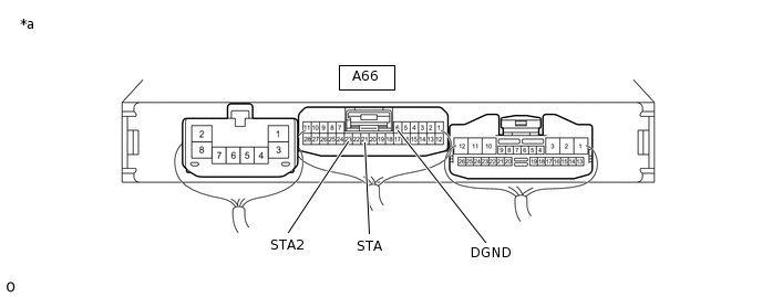
*a
Component with harness connected
(Engine Stop and Start ECU)
-
-
Connect an oscilloscope to terminals A66-21 (STA), A66-23 (STA2) and A66-6 (DGND).
-
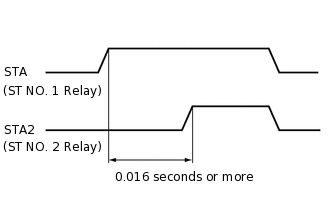
Check the waveform immediately after turning the ignition switch START.
Item
Condition
Tester Connection
A66-21 (STA) - A66-6 (DGND)
A66-23 (STA2) - A66-6 (DGND)
Condition
Engine started by ignition or starter switch assembly (w/o Entry and Start System) or push start switch assembly (w/ Entry and Start System) operation
Result
Result
Proceed to
Time between ST NO. 1 relay (for starter pinion) turning on and ST NO. 2 relay (for starter motor) turning on becomes 0.016 seconds or more
A
Time between ST NO. 1 relay (for starter pinion) turning on and ST NO. 2 relay (for starter motor) turning on becomes less than 0.016 seconds
B