CYLINDER BLOCK INSPECTION

PROCEDURE
-
INSPECT CYLINDER BLOCK OIL ORIFICE
-
Check the cylinder block oil orifice for damage or clogging.
If necessary, replace the cylinder block oil orifice.
-
-
INSPECT OIL CHECK VALVE SUB-ASSEMBLY
-
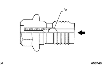
*a Ball 
Push Push the ball of the oil check valve sub-assembly with a wooden stick to check if it is stuck.
If the ball of the oil check valve sub-assembly, replace the oil check valve sub-assembly.
-
-
INSPECT NO. 1 OIL NOZZLE SUB-ASSEMBLY
-
Check the No. 1 oil nozzle sub-assembly for damage or clogging.
If necessary, replace the No. 1 oil nozzle sub-assembly.
-
-
CLEAN CYLINDER BLOCK SUB-ASSEMBLY
-
Using a gasket scraper, remove all the gasket material from the top surface of the cylinder block sub-assembly.
-
Using a soft brush and solvent, thoroughly clean the cylinder block sub-assembly.
-
-
INSPECT CYLINDER BLOCK SUB-ASSEMBLY FOR WARPAGE
-
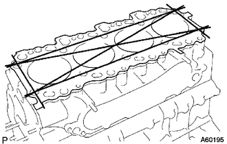
Using a precision straightedge and feeler gauge, measure the surface of the cylinder block sub-assembly that contacts the cylinder head sub-assembly for warpage.
Maximum warpage 0.1 mm (0.00394 in.) If the warpage is more than the maximum, replace the cylinder block sub-assembly.
-
Visually check the cylinders for vertical scratches.
If deep scratches are present, rebore all 4 cylinders. If necessary, replace the cylinder block sub-assembly.
-
-
INSPECT CYLINDER BORE
-
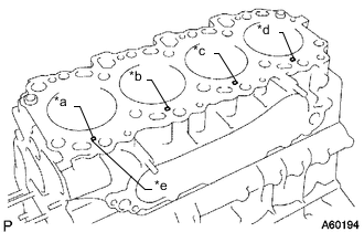
*a No. 1 *b No. 2 *c No. 3 *d No. 4 *e Mark 1, 2 or 3 Inspect the cylinder bore diameter.
Tech Tips
There are 3 standard cylinder bore diameter sizes, marked 1, 2 and 3 accordingly. The mark is stamped on the cylinder block sub-assembly.
-
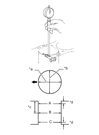
*a Axial Direction *b Thrust Direction *c Center *d 10 mm (0.394 in.) Front 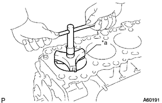
*a Ridge Reamer Using a cylinder gauge, measure the cylinder bore diameter at positions A, B and C in the thrust and axial directions.
Reference Value (New parts) Item Specified Condition STD Mark 1 92.00 to 92.01 mm (3.6220 to 3.6224 in.) STD Mark 2 92.01 to 92.02 mm (3.6224 to 3.6228 in.) STD Mark 3 92.02 to 92.03 mm (3.6228 to 3.6232 in.) O/S 0.50 92.50 to 92.53 mm (3.6417 to 3.6429 in.) Maximum Diameter Item Specified Condition STD 92.23 mm (3.6311 in.) O/S 0.50 92.73 mm (3.6508 in.) If the diameter is more than the maximum, rebore all 4 cylinders. If necessary, replace the cylinder block sub-assembly.
If the wear is less than 0.2 mm (0.00787 in.), using a ridge reamer, grind the top of the cylinder.
-
-
-
CLEAN PISTON
-
Using a groove cleaning tool or broken ring, clean the piston ring grooves.
-
Using solvent and a brush, thoroughly clean the piston.
Note
Do not use a wire brush.
-
-
INSPECT PISTON WITH PIN SUB-ASSEMBLY
Tech Tips
When replacing the piston sub-assembly (w/ pin) with a supply part,there are a number of piston diameter sizes to choose from, but there is only one size of piston pin diameter.
-
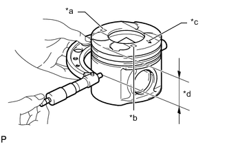
*a Size Mark *b Piston Pin Hole Inside Diameter Mark *c Front Mark (Arrow) *d Distance Using a micrometer, measure the piston diameter according to the following conditions: 1) measure at a right angle to the piston center line, and 2) measure at the indicated distance from the piston head.
Standard Distance 65 mm (2.56 in.) Reference Value (New parts) Item Specified Condition STD Mark 1 91.92 to 91.93 mm (3.6189 to 3.6193 in.) STD Mark 2 91.93 to 91.94 mm (3.6193 to 3.6197 in.) STD Mark 3 91.94 to 91.95 mm (3.6197 to 3.6201 in.) O/S 0.50 92.42 to 92.45 mm (3.6386 to 3.6398 in.) Standard Pin Hole Inside Diameter Item Specified Condition Mark A 33.998 to 34.002 mm (1.3385 to 1.3387 in.) Mark B 34.002 to 34.006mm (1.3387 to 1.3388 in.) Mark C 34.006 to 34.010 mm (1.3388 to 1.3390 in.) -
Using a micrometer, measure the piston pin diameter.
Standard Piston Pin Diameter Item Specified Condition Mark A 33.996 to 34.000 mm (1.3384 to 1.3386 in.) Mark B 34.000 to 34.004 mm (1.3386 to 1.3387 in.) Mark C 34.004 to 34.008 mm (1.3387 to 1.3389 in.) -
Subtract the piston pin diameter measurement from the piston pin hole inside diameter measurement.
Standard oil clearance 0.002 to 0.006 mm (0.0000787 to 0.000236 in.) If the oil clearance is not within the specified range, replace the piston with pin sub-assembly.
-
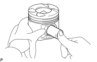
Inspect the piston pin fit.
-
At 80°C (176°F), check that the piston pin can be pushed into the piston pin hole with your thumb.
If the pin can be installed at a lower temperature, replace the piston with pin sub-assembly.
-
-
-
INSPECT PISTON OIL CLEARANCE
-
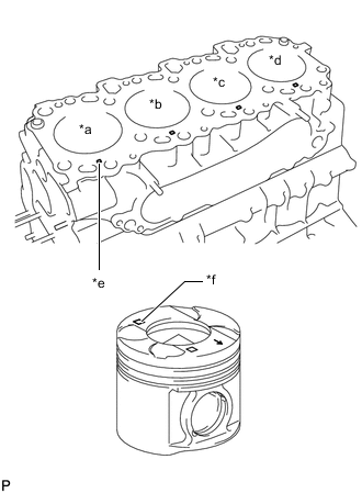
*a No. 1 *b No. 2 *c No. 3 *d No. 4 *e Mark 1, 2 or 3 *f Size Mark Measure the cylinder bore diameter in the thrust direction.
-
Subtract the piston diameter measurement from the cylinder bore diameter measurement.
Standard oil clearance 0.07 to 0.09 mm (0.00276 to 0.00354 in.) Maximum oil clearance 0.16 mm (0.00639 in.) If the oil clearance is more than the maximum, replace all 4 pistons and rebore all 4 cylinders.
If necessary, replace the cylinder block sub-assembly.
Tech Tips
When the cylinder block sub-assembly is replaced, use a piston with the same number mark as the cylinder diameter marked on the new cylinder block sub-assembly.
-
-
INSPECT RING GROOVE CLEARANCE
-
Using a feeler gauge, measure the clearance between a new piston ring and the wall of the ring groove.
Standard Groove Clearance Item Specified Condition No. 1 piston ring 0.060 to 0.100 mm (0.00236 to 0.00394 in.) No. 2 piston ring 0.050 to 0.095 mm (0.00197 to 0.00374 in.) Oil ring 0.030 to 0.075 mm (0.00118 to 0.00295 in.) Maximum groove clearance 0.20 mm (0.0787 in.) If the result is not as specified, replace the piston with pin sub-assembly.
-
-
INSPECT PISTON RING END GAP
-
Insert the piston ring into the cylinder bore.
-
Using a piston, push the piston ring a little beyond the bottom of the ring travel, 120 mm (4.72 in.) from the top of the cylinder block sub-assembly.
-
Using a feeler gauge, measure the end gap.
Standard End Gap Item Specified Condition No. 1 piston ring 0.27 to 0.39 mm (0.0106 to 0.0154 in.) No. 2 piston ring 0.47 to 0.62 mm (0.0185 to 0.0244 in.) Oil ring 0.20 to 0.40 mm (0.00787 to 0.0157 in.) Maximum End Gap Item Specified Condition No. 1 piston ring 1.21 mm (0.0476 in.) No. 2 piston ring 1.44 mm (0.0567 in.) Oil ring 1.22 mm (0.0480 in.) If the end gap is more than the maximum, replace the piston ring.
If the end gap is more than the maximum even with a new piston ring, rebore all 4 cylinders or replace the cylinder block sub-assembly.
-
-
INSPECT PISTON PIN OIL CLEARANCE
-
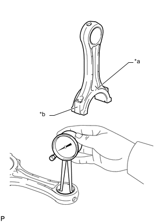
*a Front Mark *b Connecting Rod Bush Inside Diameter Mark A, B or C Using a caliper gauge, measure the inside diameter of the connecting rod bush.
Standard Bush Inside Diameter Item Specified Condition Mark A 34.012 to 34.016 mm (1.3390 to 1.3392 in.) Mark B 34.016 to 34.020 mm (1.3392 to 1.3393 in.) Mark C 34.020 to 34.024 mm (1.3393 to 1.3395 in.) -
Subtract the piston pin diameter measurement from the connecting rod bush inside diameter measurement.
Standard oil clearance 0.012 to 0.020 mm (0.000472 to 0.000878 in.) Maximum oil clearance 0.03 mm (0.0118 in.) If the oil clearance is more than the maximum, replace the connecting rod sub-assembly.
If necessary, replace the piston with pin sub-assembly.
-
-
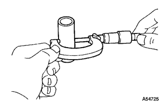
INSPECT CONNECTING ROD SUB-ASSEMBLY
-
Using a rod aligner and feeler gauge, check the connecting rod alignment.
-
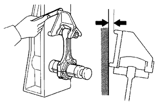
Check if the connecting rod sub-assembly is bent.
Maximum bend 0.03 mm (0.00118 in.) per 100 mm (3.94 in.) If the bend is more than the maximum, replace the connecting rod sub-assembly.
-
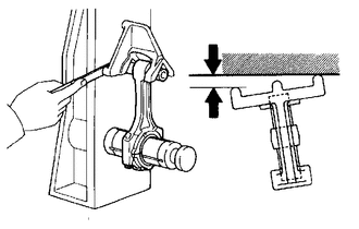
Check if the connecting rod sub-assembly is twisted.
Maximum twist 0.15 mm (0.00591 in.) per 100 mm (3.94 in.) If the twist is more than the maximum, replace the connecting rod sub-assembly.
-
-
-
INSPECT CONNECTING ROD BOLT
-
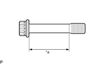
*a Tension Portion Using a vernier caliper, measure the diameter of the tension portion of the connecting rod bolt.
Standard diameter 8.5 to 8.6 mm (0.335 to 0.339 in.) Minimum diameter 8.3 mm (0.327 in.) If the diameter is less than the minimum, replace the connecting rod bolt.
-
-
INSPECT CRANKSHAFT
-
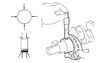
Inspect for circle runout.
-
Place the crankshaft on V-blocks.
-
Using a dial indicator, measure the circle runout at the center journal.
Maximum circle runout 0.03 mm (0.00118 in.) If the circle runout is more than the maximum, replace the crankshaft.
-
-
Inspect the main journals and crank pins.
-
Using a micrometer, measure the diameter of each main journal and crank pin.
Standard Main Journal Diameter Item Specified Condition Mark 1 69.994 to 70.000 mm (2.7557 to 2.7559 in.) Mark 2 69.988 to 69.994 mm (2.7554 to 2.7557 in.) Mark 3 69.982 to 69.988 mm (2.7552 to 2.7554 in.) U/S 0.25 69.745 to 69.755 mm (2.7459 to 2.7463 in.) U/S 0.50 69.495 to 69.505 mm (2.7360 to 2.7364 in.) Standard Crank Pin Diameter Item Specified Condition Mark 1 58.994 to 59.000 mm (2.3226 to 2.3228 in.) Mark 2 58.988 to 58.994 mm (2.3224 to 2.3226 in.) Mark 3 58.982 to 58.988 mm (2.3221 to 2.3224 in.) If the diameter is not as specified, check the connecting rod oil clearance (Click here) and crankshaft oil clearance Click here. If necessary, grind or replace the crankshaft.
-
Check each main journal and crank pin for taper and out-of-round.
Maximum taper and out-of-round 0.02 mm (0.000787 in.) If the taper and out-of-round is more than the maximum, replace the crankshaft.
-
-
If necessary, grind and hone the main journals and/or crank pins.
-
Grind and hone the main journals and/or crank pins to the finished undersized diameter (refer to the procedures above).
-
Install new main journal and/or crank pin undersized bearings.
-
-
-
INSPECT CRANKSHAFT BEARING CAP SET BOLT
-
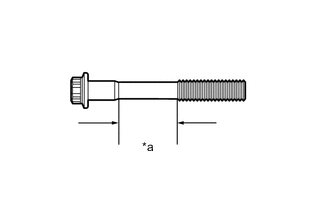
*a Measuring Area Using a vernier caliper, measure the diameter of the crankshaft bearing cap set bolt in the measuring area.
Standard diameter 13.5 to 14.0 mm (0.531 to 0.551 in.) Minimum diameter 12.6 mm (0.496 in.) If the diameter is less than the minimum, replace the crankshaft bearing cap set bolt.
-