INTAKE MANIFOLD DISASSEMBLY
PROCEDURE
-
REMOVE MANIFOLD ABSOLUTE PRESSURE SENSOR
-
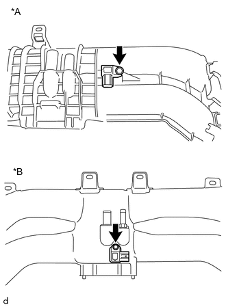
Text in Illustration *A for Resin Intake Manifold *B for Aluminum Intake Manifold Remove the bolt and manifold absolute pressure sensor from the intake manifold.
-
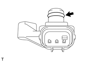
Remove the O-ring from the manifold absolute pressure sensor.
-
-
REMOVE PURGE VALVE
-
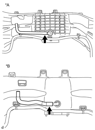
Text in Illustration *A for Resin Intake Manifold *B for Aluminum Intake Manifold Disconnect the No. 1 fuel vapor feed hose from the intake manifold.
-
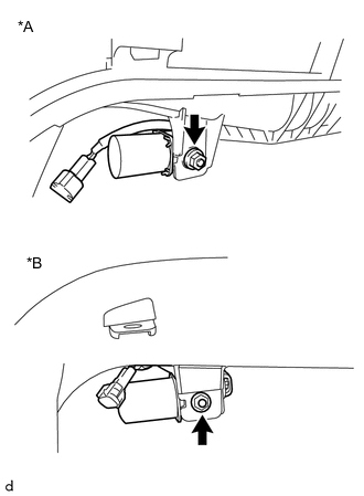
Text in Illustration *A for Resin Intake Manifold *B for Aluminum Intake Manifold Remove the nut and purge valve.
-
-
REMOVE CAP (for Automatic Transmission)
-
Remove the cap from the intake manifold.
-
-
REMOVE FUEL DELIVERY PIPE (for Bank 2)
-
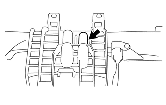
Disconnect the No. 2 fuel delivery pipe sub-assembly from the fuel delivery pipe.
Note
-
If the connector and pipe are stuck, pinch the fuel delivery pipe by hand and push and pull the connector to disconnect it
-
Do not allow any scratches or foreign matter on the parts when disconnecting them, as the No. 2 fuel delivery pipe sub-assembly joint contains the O-rings that seal the plug.
-
Do not use any tools to separate the pipe and connector.
-
Do not forcibly bend, twist or turn the nylon tube.
-
If the pipe and connector are stuck together, pinch the tube between your fingers and turn it carefully to free it. Then, disconnect the No. 2 fuel delivery pipe sub-assembly.
-
Protect the disconnected part by covering it with a plastic bag and tape after disconnecting the No. 2 fuel delivery pipe sub-assembly.
-
Check that the top hat cannot be pulled out.
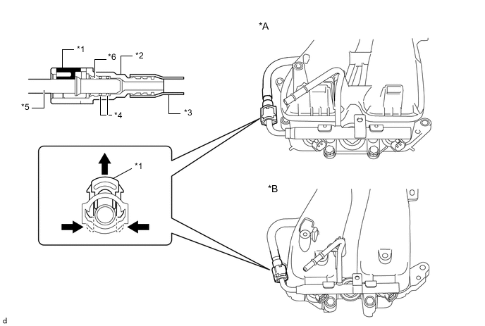
Text in Illustration *A for Resin Intake Manifold *B for Aluminum Intake Manifold *1 Retainer *2 No. 2 Fuel Delivery Pipe Sub-assembly Connector *3 Nylon Tube *4 O-ring *5 fuel delivery pipe *6 Top Hat -
-
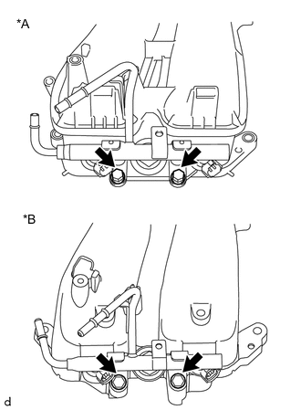
Text in Illustration *A for Resin Intake Manifold *B for Aluminum Intake Manifold Remove the 2 bolts and the fuel delivery pipe from the intake manifold.
-
Remove the 2 O-rings.
-
-
REMOVE FUEL DELIVERY PIPE (for Bank 1)
Tech Tips
Use the same procedure described for the fuel delivery pipe (for bank 2).
-
REMOVE NO. 2 FUEL DELIVERY PIPE SUB-ASSEMBLY
-
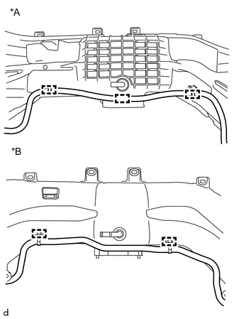
Text in Illustration *A for Resin Intake Manifold *B for Aluminum Intake Manifold Disengage the 3 clamps and remove the No. 2 fuel delivery pipe sub-assembly from the intake manifold. (for resin intake manifold)
-
Disengage the 2 clamps and remove the No. 2 fuel delivery pipe sub-assembly from the intake manifold. (for aluminum intake manifold)
-