METER / GAUGE SYSTEM Speedometer Malfunction
DESCRIPTION
The combination meter assembly controls the speedometer in accordance with the vehicle speed signals from the skid control ECU (brake actuator assembly) through the CAN communication system.
WIRING DIAGRAM
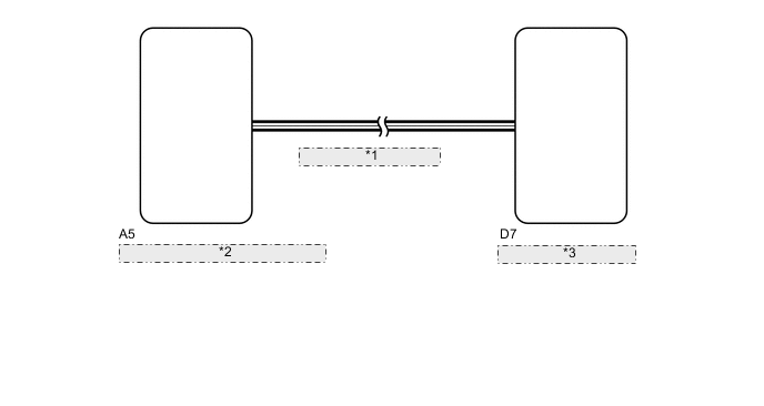
| *1 | CAN Communication Line |
| *2 | Skid Control ECU (Brake Actuator Assembly) |
| *3 | Combination Meter Assembly |
PROCEDURE
-
CHECK FOR DTC (METER / GAUGE SYSTEM)
-
Check if meter / gauge system DTCs are output Click here.
OK DTCs are not output.
NG 
GO TO DIAGNOSTIC TROUBLE CODE CHART Click here
OK 
-
-
CHECK FOR DTC (VEHICLE STABILITY CONTROL SYSTEM)
-
Check if the vehicle stability control system outputs DTCs Click here.
OK DTCs are not output.
NG
GO TO VEHICLE STABILITY CONTROL SYSTEM Click here
OK
-
-
PERFORM ACTIVE TEST USING GTS (SPEED METER OPERATION)
-
Connect the GTS to the DLC3.
-
Turn the ignition switch to ON.
-
Turn the GTS on.
-
Enter the following menus: Body Electrical / Combination Meter / Active Test.
-
According to the display on the tester, perform the Active Test.
Combination Meter Tester Display Test Part Control Range Diagnostic Note Speed Meter Operation Speedometer 0, 40, 80, 120, 160, 200, 240 km/h - OK The vehicle speed displayed on the tester is approximately the same as that of the speedometer reading.
OK
REPLACE SKID CONTROL ECU Click here
NG
REPLACE COMBINATION METER ASSEMBLY Click here
-