OUTER REAR VIEW MIRROR DISASSEMBLY
CAUTION / NOTICE / HINT
Tech Tips
-
Use the same procedure for the RH side and LH side.
-
The following procedure is for the LH side.
PROCEDURE
-
REMOVE OUTER MIRROR
-
REMOVE OUTER MIRROR COVER WITH OUTER MIRROR HOLE COVER (w/o Panoramic View Monitor System)
-
REMOVE OUTER MIRROR COVER (w/o Panoramic View Monitor System)
-
REMOVE OUTER MIRROR COVER (w/ Panoramic View Monitor System)
-
REMOVE OUTER MIRROR HOLE COVER WITH SIDE TELEVISION CAMERA ASSEMBLY (w/ Panoramic View Monitor System)
-
REMOVE SIDE TELEVISION CAMERA ASSEMBLY (w/ Panoramic View Monitor System)
-
REMOVE NO. 2 OUTER MIRROR COVER
-
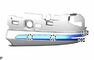
Disengage the 2 claws and 2 guides to remove the No. 2 outer mirror cover.
-
-
REMOVE SIDE TURN SIGNAL LIGHT ASSEMBLY
-
REMOVE OUTER MIRROR RETRACTOR (w/ Power Retract Mirror)
-
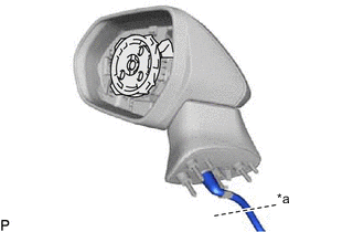
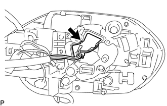
*a Cut here Cut the wire harness sub-assembly at the position shown in the illustration.
-
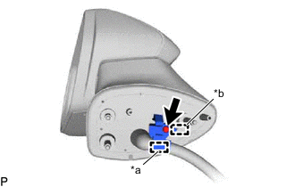
*a Clamp *b Guide Disengage the clamp.
-
Remove the screw.
-
Disengage the guide and remove the bracket.
-
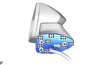
Disengage the 8 guides and remove the gasket sub-assembly.
Note
Make sure to replace the gasket sub-assembly with a new one.
-
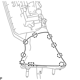
Disengage the 8 claws and guide to remove the lower cover.
Note
Make sure to replace the lower cover with a new one.
-
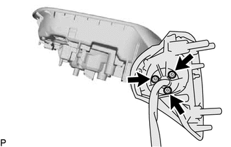
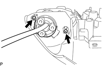
Using a T25 "TORX" socket wrench, remove the 3 screws and base sub-assembly.
Note
Make sure to replace the screw with a new one.
-
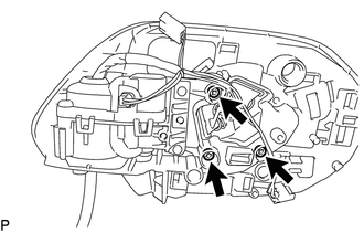
Remove the 3 screws.
-
Disconnect the connector.
-
Disengage the 2 clamps.
-
Disconnect the connector to remove the actuator sub-assembly.
-
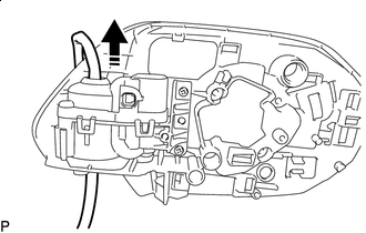

Remove in this Direction Pull the wire harness sub-assembly through the frame sub-assembly as shown in the illustration to remove the wire harness sub-assembly.
Note
Make sure to replace the wire harness sub-assembly with a new one.
-
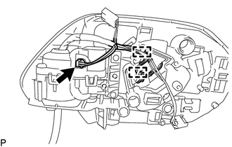
Remove the 2 screws.
-
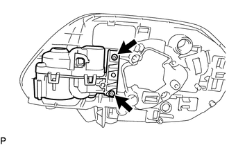
Remove the 2 screws and frame sub-assembly from the housing.
Note
Make sure to replace the frame sub-assembly with a new one.
-