BRAKE ACTUATOR(for RHD) INSTALLATION
PROCEDURE
-
INSTALL NO. 2 FUEL TUBE CLAMP
-
Engage the claw to install the No. 2 fuel tube clamp to the brake actuator bracket assembly.
-
-
INSTALL BRAKE ACTUATOR BRACKET CUSHION
-
Install the brake actuator bracket cushion to the brake actuator bracket assembly.
-
-
INSTALL NO. 1 BRAKE ACTUATOR CASE COLLAR
-
Install the No. 1 brake actuator case collar to the brake actuator bracket cushion.
-
-
INSTALL BRAKE ACTUATOR ASSEMBLY
-
Temporarily install the brake actuator assembly with the 2 nuts and a new bolt.
-
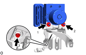
Fully tighten the 2 nuts and bolt in the order shown in the illustration.
- Torque:
- 6.5 N*m { 66 kgf*cm, 58 in.*lbf }
Note
-
Do not remove the hole plugs of a new brake actuator assembly before connecting the brake tubes because the brake actuator assembly is filled with brake fluid.
-
Do not hold the brake actuator assembly by the connector.
-
-
INSTALL BRAKE ACTUATOR WITH BRACKET
-
Temporarily install the brake actuator with bracket to the vehicle body with the bolt and 2 nuts.
-
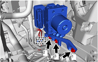
Fully tighten the bolt and 2 nuts in the order shown in the illustration.
- Torque:
- 19 N*m { 194 kgf*cm, 14 ft.*lbf }
Note
Do not damage the brake tubes.
-
Engage the 2 clamps to install the fuel main tube and fuel tank to canister tube to the No. 2 fuel tube clamp.
-
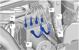
*a From 1st Chamber of Brake Booster with Master Cylinder Assembly *b From 2nd Chamber of Brake Booster with Master Cylinder Assembly *c To Front Wheel Cylinder Assembly LH *d To Rear Wheel Cylinder Assembly RH *e To Rear Wheel Cylinder Assembly LH *f To Front Wheel Cylinder Assembly RH Temporarily tighten each brake tube to the correct position on the brake actuator assembly as shown in the illustration.
-
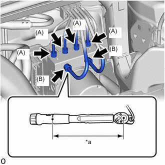
*a Torque Wrench Fulcrum Length Using a 10 mm and 12 mm union nut wrench, connect the 6 brake tubes to the brake actuator assembly.
- Torque:
- Specified tightening torque (A)
- 15.2 N*m { 155 kgf*cm, 11 ft.*lbf }
- Specified tightening torque (B)
- 19.5 N*m { 199 kgf*cm, 14 ft.*lbf }
Note
-
Do not kink or damage the brake tubes.
-
Do not allow the brake tubes to twist or interfere with other parts or the vehicle body during tightening.
-
Do not allow any foreign matter such as dirt or dust to enter the brake tubes from the connecting parts.
Tech Tips
-
Calculate the torque wrench reading when changing the fulcrum length of the torque wrench.
-
When using a union nut wrench (fulcrum length of 22 mm (0.866 in.)) + torque wrench (fulcrum length of 162 mm (6.38 in.)) (A): 13.4 N*m (137 kgf*cm, 10 ft.*lbf)
-
When using a union nut wrench (fulcrum length of 20 mm (0.787 in.)) + torque wrench (fulcrum length of 162 mm (6.38 in.)) (B): 17.4 N*m (177 kgf*cm, 13 ft.*lbf)
-
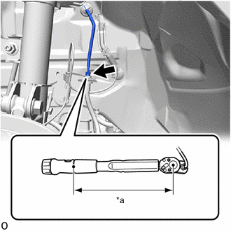
*a Torque Wrench Fulcrum Length Using a 10 mm union nut wrench, connect the brake tube to the front flexible hose.
- Torque:
- Specified tightening torque
- 15.2 N*m { 155 kgf*cm, 11 ft.*lbf }
Note
-
Do not kink or damage the brake tubes.
-
Do not allow the brake tubes to twist or interfere with other parts or the vehicle body during tightening.
-
Do not allow any foreign matter such as dirt or dust to enter the brake tubes from the connecting parts.
Tech Tips
-
Calculate the torque wrench reading when changing the fulcrum length of the torque wrench.
-
When using a union nut wrench (fulcrum length of 22 mm (0.866 in.)) + torque wrench (fulcrum length of 162 mm (6.38 in.)): 13.4 N*m (137 kgf*cm, 10 ft.*lbf)
-
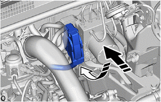

Connect the connector 
Lock the lock lever Connect the connector to the brake actuator assembly and lock the lock lever.
Note
-
Make sure that the actuator connector can be connected smoothly. Do not allow water, oil or dirt to enter the connector.
-
Make sure that the connector is locked securely.
-
-
-
INSTALL SECURITY HORN ASSEMBLY (w/ Security Horn)
-
INSTALL BATTERY
-
INSTALL OUTER COWL TOP PANEL SUB-ASSEMBLY
-
INSTALL COWL BODY MOUNTING REINFORCEMENT RH
-
INSTALL COWL BODY MOUNTING REINFORCEMENT LH
-
INSTALL WATER GUARD PLATE LH
-
INSTALL NO. 1 HEATER AIR DUCT SPLASH SHIELD SEAL
-
INSTALL WINDSHIELD WIPER MOTOR AND LINK ASSEMBLY
-
CONNECT CABLE TO NEGATIVE BATTERY TERMINAL
Note
When disconnecting the cable, some systems need to be initialized after the cable is reconnected.
-
BLEED BRAKE SYSTEM
-
INSPECT BRAKE ACTUATOR USING GTS
-
PERFORM SYSTEM VARIANT LEARNING
-
CHECK FOR AND CLEAR DTCS