OUTPUT SHAFT REASSEMBLY
CAUTION / NOTICE / HINT
When replacing any tapered roller bearing, replace both the tapered roller bearing and tapered roller bearing outer race with new ones.
PROCEDURE
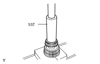
INSTALL FRONT OUTPUT SHAFT BEARING
-
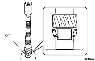
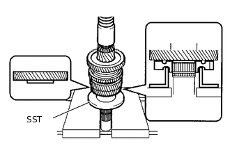
Using SST and a press, install the front output shaft bearing to the output shaft.
09710-22021
09710-01051
Note:Do not damage or deform the cage of the front output shaft bearing.
-
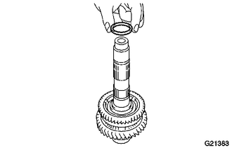
INSTALL 1ST GEAR NEEDLE ROLLER BEARING
-
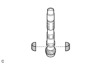
Coat the 1st gear needle roller bearing with gear oil, and install it to the output shaft.
-
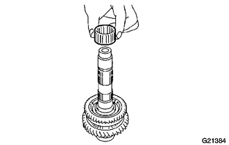
INSTALL 1ST GEAR
-
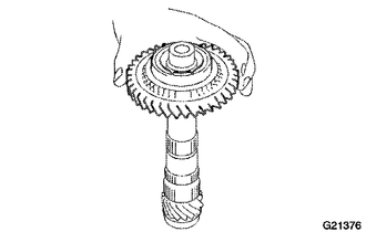
Coat the 1st gear with gear oil, and install it to the output shaft.
-
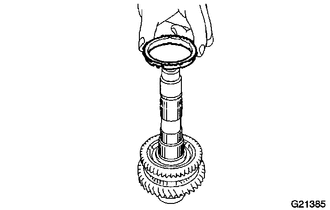
INSTALL 1ST GEAR SYNCHRONIZER RING
-
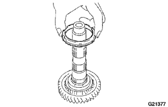
Coat the 1st gear synchronizer ring with gear oil, and install it to the 1st gear.
-
INSTALL NO. 1 TRANSMISSION CLUTCH HUB
-
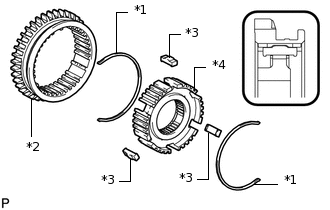
*1
No. 1 Shifting Key Spring
*2
Reverse Gear
*3
No. 1 Shifting Key
*4
No. 1 Transmission Clutch Hub
Install the reverse gear to the No. 1 transmission clutch hub, and then install the 3 No. 1 shifting keys and 2 No. 1 shifting key springs.
Note:Assemble the reverse gear and No. 1 transmission clutch hub in the correct order as shown in the illustration.
-
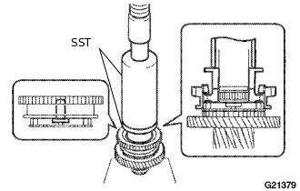
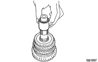
Using SST and a press, install the No. 1 transmission clutch hub to the output shaft.
09316-60011
09316-00011
09316-00071
Note:Install the No. 1 transmission clutch hub in the correct direction as shown in the illustration.
-
INSTALL NO. 1 CLUTCH HUB SHAFT SNAP RING
-
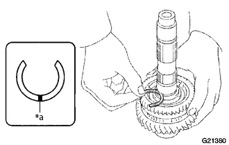
*a
Mark
Select a new No. 1 clutch hub shaft snap ring that allows for minimum axial play.
Standard Clearance
0 to 0.1 mm (0 to 0.00393 in.)
No. 1 Clutch Hub Shaft Snap Ring Thickness
Part No.
Mark
Thickness
mm (in.)
90520-32014
A
2.28 (0.0898)
90520-32015
B
2.34 (0.0921)
90520-32016
C
2.40 (0.0945)
90520-32017
D
2.46 (0.0969)
90520-32018
E
2.52 (0.0992)
90520-32019
F
2.58 (0.1016)
-
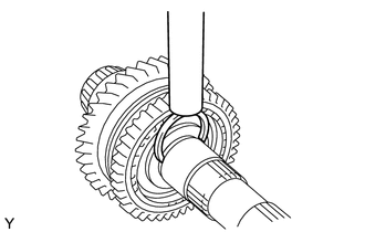
Using a brass bar and a hammer, install the No. 1 clutch hub shaft snap ring to the output shaft.
Tip:Use a piece of cloth to keep the No. 1 clutch hub shaft snap ring from flying off.
-
INSTALL 2ND GEAR BEARING SPACER
-
Coat the 2nd gear bearing spacer with gear oil, and install it to the output shaft.
-
INSTALL 2ND GEAR NEEDLE ROLLER BEARING
-
Coat the 2nd gear needle roller bearing with gear oil, and install it to the output shaft.
-
INSTALL 2ND GEAR SYNCHRONIZER RING
-
Coat the 2nd gear synchronizer ring with gear oil, and install it to the reverse gear.
-
INSTALL 2ND GEAR
-
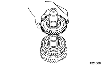
Coat the 2nd gear with gear oil, and install it to the output shaft.
-
INSTALL 3RD DRIVEN GEAR
-
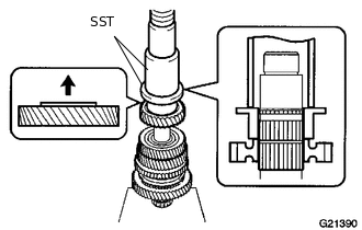
Using SST and a press, install the 3rd driven gear to the output shaft.
09316-60011
09316-00041
Note:Install the 3rd driven gear while aligning the cutout of the 2nd gear synchronizer ring and No. 1 shifting key.
-
INSTALL OUTPUT SHAFT SPACER
-
Install the output shaft spacer to the output shaft.
-
INSTALL 4TH DRIVEN GEAR
-
Using SST and a press, install the 4th driven gear to the output shaft.
09223-00010
09316-60011
09316-00021
-
INSTALL 5TH DRIVEN GEAR
-
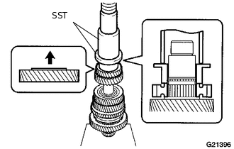
Using SST and a press, install the 5th driven gear to the output shaft.
09223-00010
09316-60011
09316-00021
-
INSTALL COUNTER 5TH GEAR SHAFT SNAP RING
-
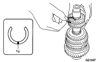
*a
Mark
Using the table below, select a new counter 5th gear shaft snap ring that makes the thrust clearance of the 5th driven gear less than 0.1 mm (0.00393 in.).
Counter 5th Gear Shaft Snap Ring Thickness
Part No.
Mark
Thickness
mm (in.)
90520-27070
A
2.22 (0.0874)
90520-27071
B
2.28 (0.0898)
90520-27072
C
2.34 (0.0921)
90520-27073
D
2.40 (0.0945)
90520-27074
E
2.46 (0.0969)
90520-27075
F
2.52 (0.0992)
90520-27076
G
2.58 (0.1016)
90520-27077
H
2.64 (0.1039)
90520-27078
J
2.70 (0.1063)
-
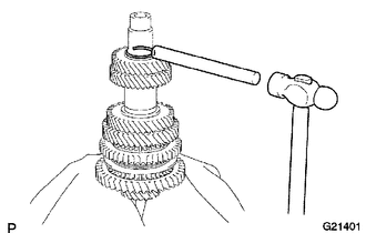
Using a brass bar and a hammer, install the counter 5th gear shaft snap ring to the output shaft.
Tip:Use a piece of cloth to keep the counter 5th gear shaft snap ring from flying off.
-
INSPECT 1ST GEAR THRUST CLEARANCE
INSPECT 2ND GEAR THRUST CLEARANCE
INSPECT 1ST GEAR RADIAL CLEARANCE
INSPECT 2ND GEAR RADIAL CLEARANCE
INSTALL REAR OUTPUT SHAFT BEARING
-
Using SST and a press, install the rear output shaft bearing to the output shaft.
09612-22011
Note:Do not damage or deform the cage of the rear output shaft bearing.
-