LIGHTING SYSTEM TERMINALS OF ECU
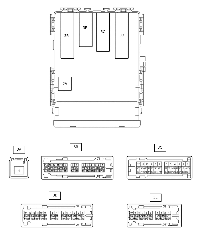
CHECK INSTRUMENT PANEL JUNCTION BLOCK ASSEMBLY, MAIN BODY ECU (MULTIPLEX NETWORK BODY ECU)
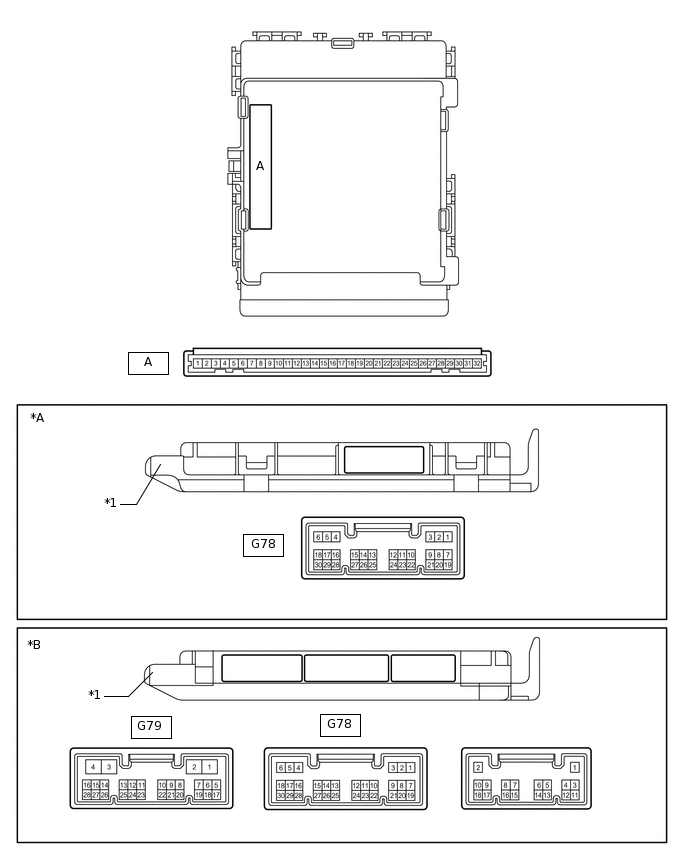
*A
Main Body ECU (Multiplex Network Body ECU) with 1 connector
*B
Main Body ECU (Multiplex Network Body ECU) with 3 connectors
*1
Main Body ECU (Multiplex Network Body ECU)
-
-
Remove the main body ECU (multiplex network body ECU) from the instrument panel junction block assembly.
for LHD:
for RHD:
Connect the instrument panel junction block assembly connectors.
Measure the voltage and resistance according to the value(s) in the table below.
Terminal No. (Symbol)
Wiring Color
Terminal Description
Condition
Specified Condition
A-32 (IG) - Body ground
-
Ignition power supply
Ignition switch ON
11 to 14 V*1
10.5 to 14 V*2
Ignition switch off
Below 1 V
A-30 (BECU) - Body ground
-
Battery power supply
Always
11 to 14 V
A-29 (ACC) - Body ground
-
ACC power supply
Ignition switch ACC
11 to 14 V
Ignition switch off
Below 1 V
A-11 (GND1) - Body ground
-
Ground
Always
Below 1 Ω
*1: w/o Stop and Start System
*2: w/ Stop and Start System
If the result is not as specified, there may be a malfunction in the wire harness or instrument panel junction block assembly.
Install the main body ECU (multiplex network body ECU).
for LHD:
for RHD:
Measure the voltage and pulse according to the value(s) in the table below.
Terminal No. (Symbol)
Wiring Color
Terminal Description
Condition
Specified Condition
G78-6 (RCTY) - Body ground
Y - Body ground
Rear door courtesy light switch RH signal
Rear door RH open
Below 1 V
Rear door RH closed
Pulse generation
G78-7 (LSFL) - Body ground
B - Body ground
Front door unlock detection switch LH signal
Front door LH unlocked
Below 1 V
Ignition switch off, all doors closed and front door LH locked
Pulse generation
G78-15 (DOMR) - Body ground
R - Body ground
Battery saving control (interior light auto cut function) signal
Battery saving control (interior light auto cut function) operating
11 to 14 V
Battery saving control (interior light auto cut function) not operating
Below 1 V
G78-18 (LSFR) - Body ground
P - Body ground
Front door unlock detection switch RH signal
Front door RH unlocked
Below 1 V
Ignition switch off, all doors closed and front door RH locked
Pulse generation
G78-19 (FRCY) - Body ground
L - Body ground
Front door courtesy light switch RH signal
Front door RH open
Below 1 V
Front door RH closed
Pulse generation
G78-1 (LCTY) - Body ground*3
W - Body ground
Rear door courtesy light switch LH signal
Rear door LH open
Below 1 V
Rear door LH closed
Pulse generation
G78-24 (LCTY) - Body ground*4
W - Body ground*1
SB - Body ground*2
Rear door courtesy light switch LH signal
Rear door LH open
Below 1 V
Rear door LH closed
Pulse generation
3C-36 - Body ground
B - Body ground
Instrument panel illumination signal
Headlight dimmer switch in TAIL
11 to 14 V
Headlight dimmer switch off
Below 1 V
3C-41 (LSR) - Body ground*5
Y - Body ground
Rear door unlock detection switch RH signal
Rear door RH unlocked
Below 1 V
Ignition switch off, all doors closed and rear door RH locked
Pulse generation
3D-35 (ILE) - Body ground
GR - Body ground
Map light and No. 1 room light signal
Map light and No. 1 room light on using illuminated entry system
Below 1 V
Map light and No. 1 room light off using illuminated entry system
11 to 14 V
3D-44 (KILE) - Body ground*6
GR - Body ground
Ignition key cylinder light signal
Ignition key cylinder light on
Below 1 V
Ignition key cylinder light off
11 to 14 V
3D-50 (BCYL) - Body ground*6
Y - Body ground
Interior light power supply
Battery saving control (interior light auto cut function) operating
Below 1 V
Battery saving control (interior light auto cut function) not operating
11 to 14 V
3E-25 (BCTL) - Body ground
P - Body ground
Interior light power supply
Battery saving control (interior light auto cut function) operating
Below 1 V
Battery saving control (interior light auto cut function) not operating
11 to 14 V
3E-32 (LSR) - Body ground*5
Y - Body ground
Rear door unlock detection switch LH signal
Rear door LH unlocked
Below 1 V
Ignition switch off, all doors closed and rear door LH locked
Pulse generation
3E-33 (BCTY) - Body ground
LG - Body ground
Back door courtesy light switch signal
Back door open
Below 1 V
Back door closed
11 to 14 V
3E-40 (FLCY) - Body ground
W - Body ground
Front door courtesy light switch LH signal
Front door LH open
Below 1 V
Front door LH closed
Pulse generation
*1: for LHD
*2: for RHD
*3: w/ Side Marker Light
*4: w/o Side Marker Light
*5: w/ Entry and Start System or Theft Deterrent System
*6: w/o Entry and Start System
CHECK CERTIFICATION ECU (SMART KEY ECU ASSEMBLY) (w/ Entry and Start System)
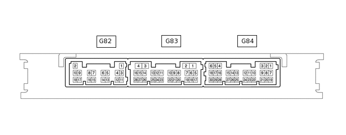
Disconnect the G82 and G84 certification ECU connectors.
Measure the voltage and resistance according to the value(s) in the table below.
Terminal No. (Symbol)
Wiring Color
Terminal Description
Condition
Specified Condition
G82-2 (+B) - Body ground
W - Body ground
Battery power supply
Always
11 to 14 V
G82-10 (CUTB) - Body ground
P - Body ground
Battery power supply
Always
11 to 14 V
G84-5 (IG) - Body ground
LG - Body ground
Ignition power supply
Ignition switch ON
11 to 14 V
Ignition switch off
Below 1 V
G82-11 (E) - Body ground
BR - Body ground
Ground
Always
Below 1 Ω
If the result is not as specified, there may be a malfunction on the wire harness side.
Reconnect the G82 and G84 certification ECU connectors.
Measure the voltage according to the value(s) in the table below.
Terminal No. (Symbol)
Wiring Color
Terminal Description
Condition
Specified Condition
G84-16 (SWIL) - Body ground
P - Body ground
Engine switch illumination operation signal
Engine switch illumination on
11 to 14 V
Engine switch illumination off
Below 1 V