OUTER MIRROR SWITCH INSPECTION
PROCEDURE
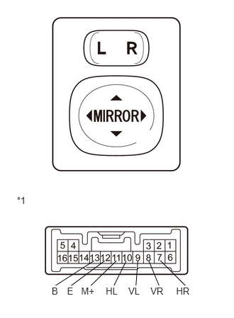
INSPECT OUTER MIRROR SWITCH ASSEMBLY (w/o Retract Mirror)
Inspect the outer mirror switch assembly.
Select "L" on the left/right adjustment switch.
Measure the resistance according to the value(s) in the table below.
Standard Resistance
Tester Connection
Switch Condition
Specified Condition
9 (VL) - 13 (B)
11 (M+) - 12 (E)
UP
Pressed
Below 1 Ω
Not pressed
10 kΩ or higher
9 (VL) - 12 (E)
11 (M+) - 13 (B)
DOWN
Pressed
Below 1 Ω
Not pressed
10 kΩ or higher
10 (HL) - 13 (B)
11 (M+) - 12 (E)
LEFT
Pressed
Below 1 Ω
Not pressed
10 kΩ or higher
10 (HL) - 12 (E)
11 (M+) - 13 (B)
RIGHT
Pressed
Below 1 Ω
Not pressed
10 kΩ or higher
If the result is not as specified, replace the outer mirror switch assembly.
Select "R" on the left/right adjustment switch.
Measure the resistance according to the value(s) in the table below.
Standard Resistance
Tester Connection
Switch Condition
Specified Condition
8 (VR) - 13 (B)
11 (M+) - 12 (E)
UP
Pressed
Below 1 Ω
Not pressed
10 kΩ or higher
8 (VR) - 12 (E)
11 (M+) - 13 (B)
DOWN
Pressed
Below 1 Ω
Not pressed
10 kΩ or higher
7 (HR) - 13 (B)
11 (M+) - 12 (E)
LEFT
Pressed
Below 1 Ω
Not pressed
10 kΩ or higher
7 (HR) - 12 (E)
11 (M+) - 13 (B)
RIGHT
Pressed
Below 1 Ω
Not pressed
10 kΩ or higher
If the result is not as specified, replace the outer mirror switch.
Table 1. Text in Illustration *1
Component without harness connected
(Outer Mirror Switch Assembly)
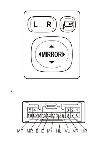
REMOVE OUTER MIRROR SWITCH ASSEMBLY (w/ Retract Mirror)
Inspect the outer mirror switch assembly.
Select "L" on the left/right adjustment switch.
Measure the resistance according to the value(s) in the table below.
Standard Resistance
Tester Connection
Switch Condition
Specified Condition
9 (VL) - 13 (B)
11 (M+) - 12 (E)
UP
Pressed
Below 1 Ω
Not pressed
10 kΩ or higher
9 (VL) - 12 (E)
11 (M+) - 13 (B)
DOWN
Pressed
Below 1 Ω
Not pressed
10 kΩ or higher
10 (HL) - 13 (B)
11 (M+) - 12 (E)
LEFT
Pressed
Below 1 Ω
Not pressed
10 kΩ or higher
10 (HL) - 12 (E)
11 (M+) - 13 (B)
RIGHT
Pressed
Below 1 Ω
Not pressed
10 kΩ or higher
If the result is not as specified, replace the outer mirror switch assembly.
Select "R" on the left/right adjustment switch.
Measure the resistance according to the value(s) in the table below.
Standard Resistance
Tester Connection
Switch Condition
Specified Condition
8 (VR) - 13 (B)
11 (M+) - 12 (E)
UP
Pressed
Below 1 Ω
Not pressed
10 kΩ or higher
8 (VR) - 12 (E)
11 (M+) - 13 (B)
DOWN
Pressed
Below 1 Ω
Not pressed
10 kΩ or higher
7 (HR) - 13 (B)
11 (M+) - 12 (E)
LEFT
Pressed
Below 1 Ω
Not pressed
10 kΩ or higher
7 (HR) - 12 (E)
11 (M+) - 13 (B)
RIGHT
Pressed
Below 1 Ω
Not pressed
10 kΩ or higher
If the result is not as specified, replace the outer mirror switch.
Table 2. Text in Illustration *1
Component without harness connected
(Outer Mirror Switch Assembly)
Check the retract switch.
Measure the resistance according to the value(s) in the table below.
Standard Resistance
Tester Connection
Condition
Specified Condition
13 (B) - 14 (MR)
15 (MF) - 12 (E)
Pushed in
Below 1 Ω
15 (MF) - 13 (B)
12 (E) - 14 (MR)
Not pushed in
Below 1 Ω
If the result is not as specified, replace the outer mirror switch assembly.