AIR CONDITIONING SYSTEM
-
CONSTRUCTION
-
A rear cooling unit assembly is used that integrates the heater and cooler.
-
The mode control door, which switches the air outlet mode, uses a laminate sliding type mode control door to achieve size and weight reduction.
-
A Revolutionary super-slim Structure (RS) type evaporator is used.
-
A Straight Flow Aluminum-II (SFA-II) heater core that is compact and offers advanced performance is used.
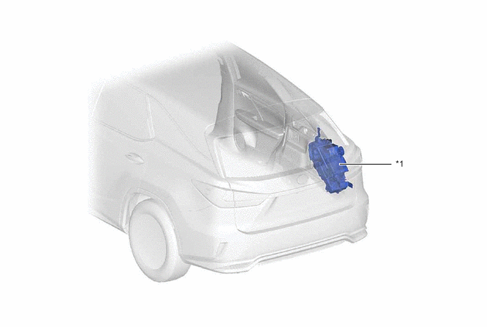
*1 Rear Cooling Unit Assembly - - -
A foam molding type rear air duct is used, improving weight reduction and heat insulation performance.
Figure 1. Rear Duct Layout
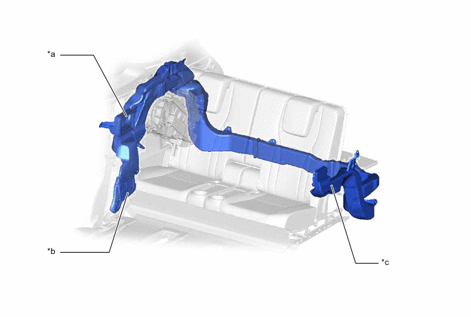
*a No. 2 Rear Seat Side Register (RH) *b No. 2 Rear Seat Footwell Register *c No. 2 Rear Seat Side Register (LH) - -
-
-
OPERATION
-
Mode Position and Damper Operation
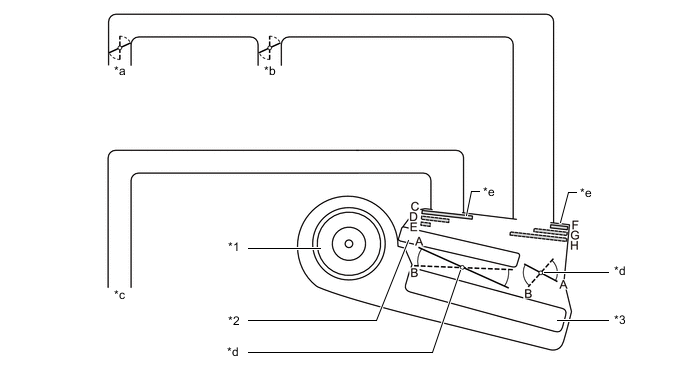
*1 Rear Blower Motor with Fan Sub-assembly *2 Heater Radiator Unit Sub-assembly *3 Rear Evaporator Sub-assembly - - *a No. 2 Rear Seat Side Register (RH) *b No. 2 Rear Seat Side Register (LH) *c No. 2 Rear Seat Footwell Register *d Air Mix Control Damper *e Mode Switching Damper - - Mode Position and Door Operation Damper Control Position Damper Position Operation Air Mix Control Damper Max COOL to Max HOT Temperature Setting A to B Varies the mixture ratio of warm air and cool air in order to continuously regulate the temperature between max hot and max cool. Mode Control Damper FACE C, F Air blows out of the No. 2 rear seat side register LH/RH. BI-LEVEL D, G Air blows out of the No. 2 rear seat side register LH/RH and No. 2 rear seat footwell register. FOOT E, H Air blows out of the rear No. 2 seat footwell register. -
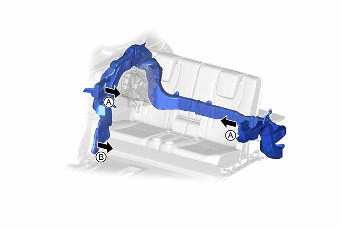
Air Outlets and Airflow Volume
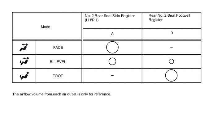
-