ECD SYSTEM, Diagnostic DTC:P0088
| DTC Code | DTC Name |
|---|---|
| P0088 | Fuel Rail / System Pressure - Too High |
DESCRIPTION
| DTC No. | Detection Item | DTC Detection Condition | Trouble Area | MIL | Memory |
|---|---|---|---|---|---|
| P0088 | Fuel Rail / System Pressure - Too High | The fuel pressure of the common rail exceeds 240000 kPa (2447 kgf/cm2, 34800 psi) (1 trip detection logic). |
|
Comes on | DTC stored |
| DTC No. | Data List |
|---|---|
| P0088 |
|
Tech Tips
-
For more information on the common rail system, refer to System Description Click here.
-
When DTC P0088 is stored, check the internal fuel pressure of the common rail assembly by entering the following menus: Powertrain / Engine and ECT / Data List / Common Rail Pressure.
Reference Engine Speed Common Rail Pressure Idling Approximately 25000 to 45000 kPa 3000 rpm (No engine load) Approximately 60000 to 95000 kPa -
Check "Common Rail Pressure" and "Target Common Rail Pressure" in the freeze frame data.
CONFIRMATION DRIVING PATTERN
| DTC No. | DTC Detection Drive Pattern |
|---|---|
| P0088 | After idling for 60 seconds, quickly increase engine speed to 2500 rpm repeatedly for 30 seconds |
MONITOR DESCRIPTION
The ECM stores this DTC if the fuel pressure inside the common rail assembly is higher than 240000 kPa (2447 kgf/cm2, 34800 psi). This DTC indicates that: 1) the pre-stroke control valve may be stuck open, or 2) there may be a short in the pre-stroke control valve circuit.
If this DTC is stored, the ECM enters fail-safe mode and limits the engine power. The ECM continues operating in fail-safe mode until the ignition switch is turned off.
CAUTION / NOTICE / HINT
Note
After replacing the ECM, the new ECM needs registration (Click here ) and initialization Click here.
Tech Tips
Read freeze frame data using the GTS. Freeze frame data records the engine condition when malfunctions are detected. When troubleshooting, freeze frame data can help determine if the vehicle was moving or stationary, if the engine was warmed up or not, and other data from the time the malfunction occurred.
PROCEDURE
-
CHECK FOR ANY OTHER DTCS OUTPUT (IN ADDITION TO DTC P0088)
-
Connect the GTS to the DLC3.
-
Turn the ignition switch to ON and turn the GTS on.
-
Enter the following menus: Powertrain / Engine and ECT / Trouble Codes.
-
Read Current DTCs.
Powertrain > Engine and ECT > Trouble CodesResult Result Proceed to P0088 is output A P0088 and "P0190, P0192 and/or P0193" are output B Tech Tips
When there is an open circuit in the fuel pressure sensor circuit, the fuel pressure sensor outputs the maximum value. Therefore, P0088 may be stored together with DTCs which indicate common rail fuel pressure sensor circuit malfunctions.
B 
GO TO FUEL RAIL PRESSURE SENSOR CIRCUIT Click here
A 
-
-
CHECK FREEZE FRAME DATA (COMMON RAIL PRESSURE)
-
Connect the GTS to the DLC3.
-
Turn the ignition switch to ON and turn the GTS on.
-
Enter the following menus: Powertrain / Engine and ECT / Trouble Codes.
-
Record the stored DTCs and freeze frame data.
Powertrain > Engine and ECT > Trouble CodesResult Result Proceed to Value of Common Rail Pressure is shifting towards 160000 kPa or higher in 3rd and 4th set of freeze frame data B Except above A
B 
GO TO STEP 5 Click here
A
-
-
INSPECT ECM (FUEL PRESSURE SENSOR OUTPUT VOLTAGE)
-
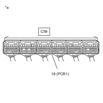
*a Component with harness connected
(ECM)
Connect the positive (+) probe of an oscilloscope to the fuel pressure sensor input terminal of the ECM connector and the negative (-) probe to the body ground.
-
Turn the ignition switch to ON.
-
Check for any noise in the waveform when vibration is applied to the wire harness and connectors between the fuel pressure sensor and ECM.
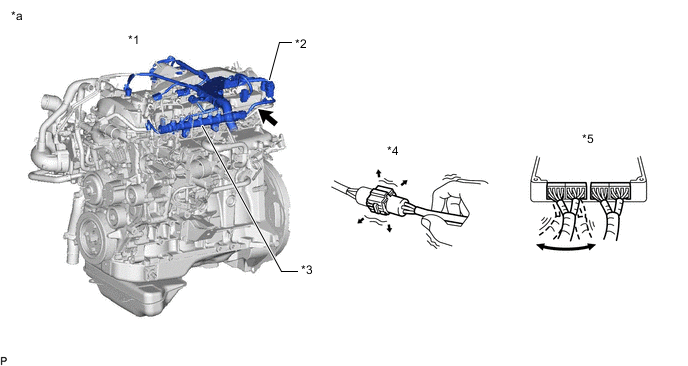
*1 Engine *2 Engine Wire *3 Common Rail Assembly (Fuel Pressure Sensor) *4 Wire to Wire *5 ECM - - *a Vibration Method (Reference) - - 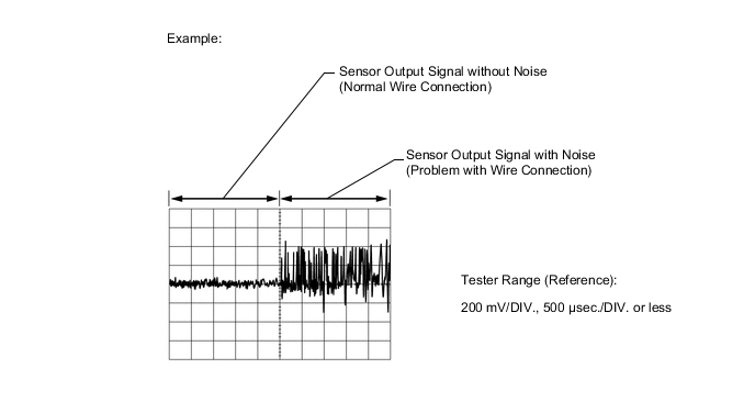
Standard Voltage Tester Connection Condition Specified Condition C59-18 (PCR1) - Body ground Vibration is applied to the wire harness and connectors No noise in the waveform Result Result Proceed to MIL comes on or noise present in the waveform B Except above A
B
REPAIR OR REPLACE HARNESS OR CONNECTOR Click here
A
-
-
PERFORM ACTIVE TEST USING GTS (ACTIVATE THE PRE-STROKE CONTROL VALVE)
-
Connect the GTS to the DLC3.
-
Turn the ignition switch to ON.
-
Turn the GTS on.
-
Enter the following menus: Powertrain / Engine and ECT / Active Test / Activate the Pre-stroke Control Valve
Powertrain > Engine and ECT > Active TestTester Display Activate the Pre-stroke Control Valve -
Perform the Active Test and check that operation sounds can be heard from the pre-stroke control valve.
Tech Tips
-
Perform this procedure with the engine stopped and check the operation sounds from outside the vehicle.
-
Check in a quiet location with the hood opened, as the operation sound is difficult to hear.
-
In order to distinguish between the operation sounds of other actuators, use the GTS to turn the Active Test on and off several times, and check for operation sounds that are synchronized with the on and off operations.
OK Operation sounds occur each time the Active Test is performed every 0.5 seconds. Result Proceed to OK NG -
OK
GO TO STEP 8 Click here
NG
-
-
REPLACE FUEL SUPPLY PUMP ASSEMBLY
-
Replace the fuel supply pump assembly.
Result Proceed to NEXT
NEXT
-
-
BLEED AIR FROM FUEL SYSTEM
-
Bleed the air from the fuel system.
Result Proceed to NEXT
NEXT
-
-
CHECK DTC OUTPUT
-
Connect the GTS to the DLC3.
-
Clear the DTCs.
Powertrain > Engine and ECT > Clear DTCs -
Turn the ignition switch off for 30 seconds or more.
-
Turn the ignition switch to ON and start the engine.
-
After idling for 60 seconds, increase the engine speed from idling to 2500 rpm repeatedly for 30 seconds.
-
Enter the following menus: Powertrain / Engine and ECT / Trouble Codes.
-
Confirm that the DTC is not output again.
Powertrain > Engine and ECT > Trouble CodesTech Tips
Perform the following procedure using the GTS to determine whether or not the DTC judgment has been carried out.
-
Enter the following menus: Powertrain / Engine and ECT / Utility / All Readiness.
Powertrain > Engine and ECT > UtilityTester Display All Readiness -
Input DTC P0088.
-
Check the DTC judgment result.
Result GTS Display Result Proceed to Pending DTC P0088 is output A All Readiness NORMAL B ABNORMAL A Tech Tips
If STATUS is INCOMPLETE or N/A, race the engine to 2500 rpm repeatedly for 30 seconds and increase the idling time.
-
B
END
A
-
-
REPLACE ECM
-
Replace the ECM.
Result Proceed to NEXT
NEXT
GO TO STEP 13 Click here
-
-
REPAIR OR REPLACE HARNESS OR CONNECTOR
-
Repair or replace the harness or connector.
Result Proceed to NEXT
NEXT
-
-
INSPECT ECM (FUEL PRESSURE SENSOR OUTPUT VOLTAGE)
-
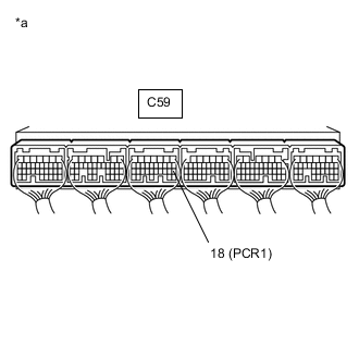
*a Component with harness connected
(ECM)
Connect the positive (+) probe of an oscilloscope to the fuel pressure sensor input terminal of the ECM connector and the negative (-) probe to the body ground.
-
Turn the ignition switch to ON.
-
Check for any noise in the waveform when vibration is applied to the wire harness and connectors between the fuel pressure sensor and ECM.
Standard Voltage Tester Connection Condition Specified Condition C59-18 (PCR1) - Body ground Vibration is applied to the wire harness and connectors No noise in the waveform Result Result Proceed to MIL comes on or noise present in the waveform A Except above B
B
GO TO STEP 13 Click here
A
-
-
REPLACE COMMON RAIL ASSEMBLY
-
Replace the common rail assembly.
Result Proceed to NEXT
NEXT
-
-
BLEED AIR FROM FUEL SYSTEM
-
Bleed the air from the fuel system.
Result Proceed to NEXT
NEXT
-
-
CONFIRM WHETHER MALFUNCTION HAS BEEN SUCCESSFULLY REPAIRED
-
Connect the GTS to the DLC3.
-
Clear the DTCs.
Powertrain > Engine and ECT > Clear DTCs -
Turn the ignition switch off for 30 seconds or more.
-
Turn the ignition switch to ON and start the engine.
-
After idling for 60 seconds, increase the engine speed from idling to 2500 rpm repeatedly for 30 seconds.
-
Confirm that the DTC is not output again.
Tech Tips
Perform the following procedure using the GTS to determine whether or not the DTC judgment has been carried out.
-
Enter the following menus: Powertrain / Engine and ECT / Utility / All Readiness.
Powertrain > Engine and ECT > UtilityTester Display All Readiness -
Input DTC P0088.
-
Check that STATUS is NORMAL. If STATUS is INCOMPLETE or N/A, race the engine to 2500 rpm repeatedly for 30 seconds and increase the idling time.
Result Proceed to NEXT -
NEXT
END
-