REAR LOWER ARM REMOVAL
CAUTION / NOTICE / HINT
Use the same procedure for the RH side and LH side.
The procedure listed below is for the LH side.
PROCEDURE
REMOVE REAR WHEEL
REMOVE REAR SUSPENSION ARM COVER
-
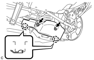
Remove the 2 bolts and disengage the 2 claws to remove the rear suspension arm cover from the rear No. 2 suspension arm assembly.
-
REMOVE REAR FLOOR SIDE MEMBER COVER LH (for LH Side)
REMOVE REAR FLOOR SIDE MEMBER COVER RH (for RH Side)
REMOVE REAR NO. 1 SUSPENSION ARM ASSEMBLY
-
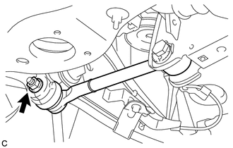
Remove the nut.
-
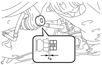
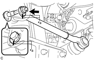
*a
1 mm or more
Install 2 spacers (SST spacer B) as shown in the illustration.
09960-20010
09961-02060
Note:As SST may be damaged, make sure that the clearance between the rear axle assembly and spacers is 1 mm (0.0394 in.) or more.
Using SST, separate the rear No. 1 suspension arm assembly from the rear axle assembly as shown in the illustration.
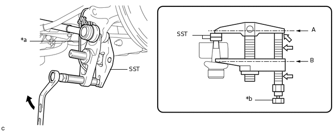
*a
Tie string without any slack
*b
Place wrench here

Turn

Molybdenum Grease
09960-20010
09961-02010
09961-02060
CAUTION:Apply molybdenum grease to the threads and end of the SST bolt.
Note:Be sure to tighten the string firmly to secure SST to the rear axle assembly to prevent SST from falling off.
Install SST so that A and B are parallel.
Be sure to place the wrench on the part indicated in the illustration.
Do not damage the ball joint dust cover.
-
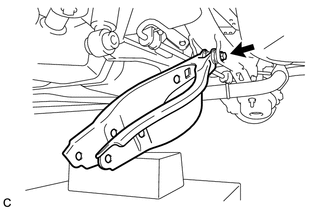
*a
Matchmark
Place matchmarks on the rear No. 1 suspension camber adjust cam, rear suspension toe adjust cam sub-assembly and rear suspension member sub-assembly.
Remove the nut, rear No. 1 suspension camber adjust cam, rear suspension toe adjust cam sub-assembly and rear No. 1 suspension arm assembly.
Note:Hold the rear suspension toe adjust cam sub-assembly while rotating the nut.
-
REMOVE REAR HEIGHT CONTROL SENSOR SUB-ASSEMBLY (w/ Height Control Sensor)
REMOVE REAR STABILIZER LINK ASSEMBLY
REMOVE REAR SUSPENSION MEMBER BRACE
REMOVE REAR COIL SPRING
REMOVE REAR UPPER COIL SPRING INSULATOR
REMOVE REAR LOWER COIL SPRING INSULATOR
REMOVE REAR NO. 2 SUSPENSION ARM ASSEMBLY
-
Remove the bolt, nut and rear No. 2 suspension arm assembly from the rear suspension member sub-assembly.
Note:Because the nut has its own stopper, do not turn the nut. Loosen the bolt with the nut secured.
-