MANUAL TRANSAXLE ASSEMBLY REMOVAL
PROCEDURE
PRECAUTION
Note:After turning the ignition switch off, waiting time may be required before disconnecting the cable from the negative (-) battery terminal. Therefore, make sure to read the disconnecting the cable from the negative (-) battery terminal notices before proceeding with work.
DISCONNECT CABLE FROM NEGATIVE BATTERY TERMINAL
Note:When disconnecting the cable, some systems need to be initialized after the cable is reconnected.
REMOVE NO. 1 ENGINE UNDER COVER
REMOVE STARTER ASSEMBLY
REMOVE FRONT EXHAUST PIPE ASSEMBLY
REMOVE FRONT LOWER BUMPER ABSORBER
REMOVE REAR ENGINE UNDER COVER RH
REMOVE REAR ENGINE UNDER COVER LH
DRAIN MANUAL TRANSAXLE OIL
REMOVE DRIVE SHAFT ASSEMBLY
DRAIN ENGINE COOLANT
REMOVE NO. 1 ENGINE COVER
REMOVE AIR CLEANER CAP SUB-ASSEMBLY WITH AIR CLEANER HOSE ASSEMBLY
REMOVE AIR CLEANER CASE SUB-ASSEMBLY
REMOVE AIR CLEANER BRACKET
-
Disengage the 3 clamps to separate the wire harness.
-
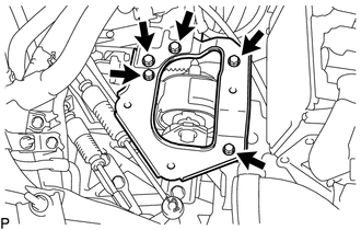
Remove the 5 bolts and air cleaner bracket.
-
DISCONNECT ENGINE WIRE
REMOVE NO. 4 WATER BY-PASS HOSE
DISCONNECT COMPRESSOR OUTLET ELBOW
DISCONNECT NO. 2 AIR HOSE
REMOVE NO. 1 AIR TUBE ASSEMBLY
-
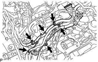
Slide the clamp and disconnect the water by-pass hose assembly from the No. 2 radiator pipe.
Slide the clamp and disconnect the radiator hose sub-assembly from the No. 1 radiator pipe.
Disengage the clamp to disconnect the water hose sub-assembly from the compressor outlet elbow.
Slide the clamp and disconnect the water hose sub-assembly from the No. 1 radiator pipe.
Slide the clamp and disconnect the outlet heater water hose from the No. 2 radiator pipe.
Remove the 2 bolts and No. 1 air tube assembly from the manual transaxle assembly.
-
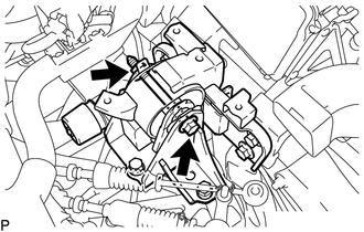
DISCONNECT TRANSMISSION CONTROL CABLE ASSEMBLY
-
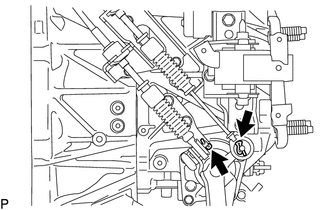
Remove the 2 clips and disconnect the transmission control cable assembly from the manual transaxle assembly.
-
Remove the 2 clips and disconnect the transmission control cable assembly from the control cable bracket.
-
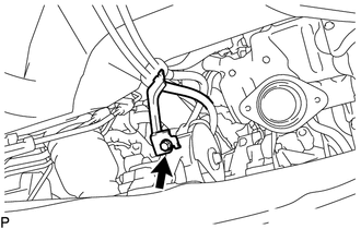
Remove the bolt to disconnect the bracket of the transmission control cable assembly from the rear engine mounting insulator.
-
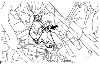
REMOVE NO. 1 CLUTCH HOUSING COVER
-
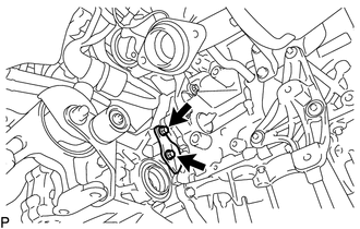
Remove the 2 bolts and No. 1 clutch housing cover.
-
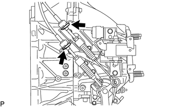
REMOVE NO. 2 MANIFOLD STAY
-
Using an E14 "TORX" socket wrench, remove the 2 bolts from the manual transaxle assembly.
Remove the nut and No. 2 manifold stay.
-
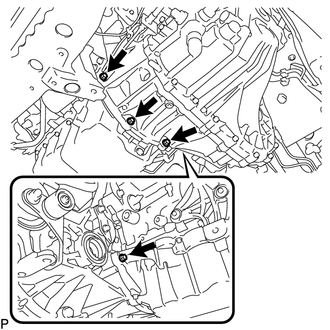
DISCONNECT CLUTCH RELEASE CYLINDER ASSEMBLY
-
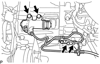
Remove the 4 bolts to disconnect the clutch release cylinder assembly and clutch flexible hose bracket from the manual transaxle assembly.
-
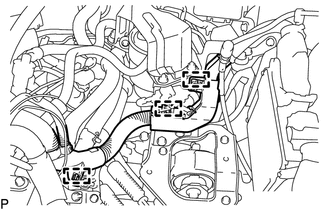
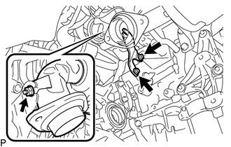
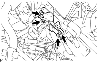
DISCONNECT WIRE HARNESS
-
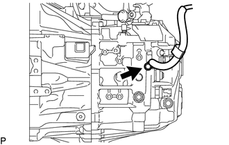
Remove the bolt to disconnect the ground cable.
-
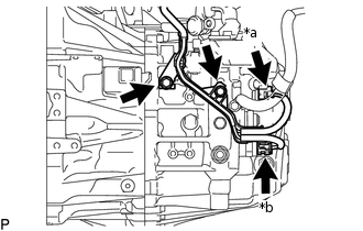
*a
Back-up Light Switch Assembly Connector
*b
Neutral Position Switch Connector
Disconnect the back-up light switch assembly connector.
Disconnect the neutral position switch connector.
Remove the 2 bolts to disconnect the wire harness.
-
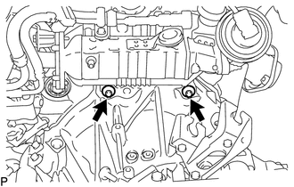
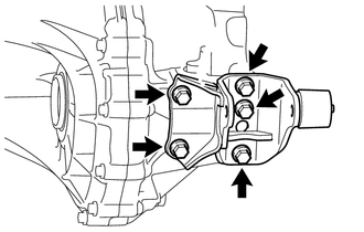
LOOSEN ENGINE AND TRANSAXLE CONNECTING BOLT
Manual transaxle assembly upper side:
-
Using an E14 "TORX" socket wrench, loosen the 2 bolts.
-
Manual transaxle assembly lower side:
-
Loosen the 4 bolts.
-
Engine mounting insulator LH side:
-
Loosen the bolt.
-
REMOVE FRONT SUSPENSION CROSSMEMBER SUB-ASSEMBLY
SUPPORT MANUAL TRANSAXLE ASSEMBLY
Support the manual transaxle assembly with a transmission jack.
Note:Secure the manual transaxle assembly to the transmission jack using a suitable adapter, such as a rope or attachment.
REMOVE FRONT CROSS MEMBER SUB-ASSEMBLY
-
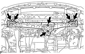
Remove the 6 bolts and front cross member sub-assembly.
-
REMOVE FRONT ENGINE MOUNTING INSULATOR
-
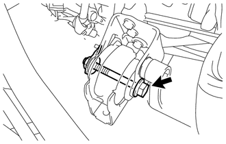
Remove the through bolt, nut and front engine mounting insulator.
-
REMOVE MANUAL TRANSAXLE ASSEMBLY
As there is very little space around the manual transaxle assembly, make sure that the manual transaxle assembly does not contact the vehicle body, clutch lines and radiator cooling fan when removing the manual transaxle assembly.
When removing the manual transaxle assembly, it is necessary to move the engine assembly and manual transaxle assembly up and down, and back and forth. Therefore, continually confirm that the parts are properly supported and stable while performing this procedure.
-
Remove the nut and through bolt to disconnect the engine mounting insulator LH from the engine mount bracket LH.
Slowly lower the transmission jack to slightly tilt the engine assembly and manual transaxle assembly.
Tip:Lower the engine assembly and manual transaxle assembly to a position where the engine mounting insulator LH can be removed.
-
Remove the 4 bolts and engine mounting insulator LH from the vehicle body.
-
Remove the 4 bolts and engine mounting bracket LH from the manual transaxle assembly.
Note:Make sure to clean the bolts and bolt holes after removing the manual transaxle assembly.
-
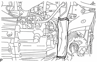
Use a cloth, etc. to protect the clutch lines as shown in the illustration.
-
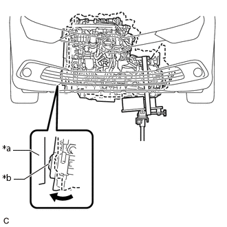
*a
Vehicle Body
*b
Crankshaft Damper Sub-assembly
Slowly lower the transmission jack to slightly tilt the engine assembly and manual transaxle assembly.
Note:Make sure that the crankshaft damper sub-assembly does not contact the vehicle body.
-
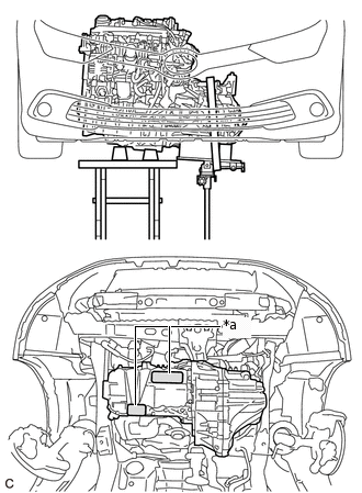
*a
Engine Support Point
Support the engine assembly with an engine lifter as shown in the illustration.
-
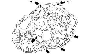
*a
E14 "TORX" Bolt
Using an E14 "TORX" socket wrench, remove the 2 bolts.
Remove the 4 bolts.
While making sure that the manual transaxle assembly does not contact the clutch lines, slowly separate the manual transaxle assembly from the engine assembly until the input shaft is clear of the diaphragm spring of the clutch cover.
Note:To prevent damage to the dowel pins, do not pry between the manual transaxle assembly and engine assembly.
Slowly lower the transmission jack to remove the manual transaxle assembly.
REMOVE REAR ENGINE MOUNTING INSULATOR
REMOVE FRONT ENGINE MOUNTING BRACKET
-
Remove the 4 bolts and front engine mounting bracket.
-
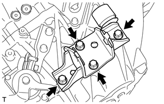
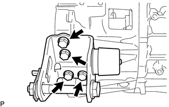
REMOVE REAR ENGINE MOUNTING BRACKET
-
Remove the 5 bolts and rear engine mounting bracket.
-