SFI SYSTEM(w/o Canister Pump Module), Diagnostic DTC:P15E517, P15E52A, P25AE00
| DTC Code | DTC Name |
|---|---|
| P15E517 | Piston Oil Cooling Pressure Sensor Circuit Voltage Above Threshold |
| P15E52A | Piston Oil Cooling Pressure Sensor Signal Stuck In Range |
| P25AE00 | Piston Cooling Oil Pressure Too Low |
DESCRIPTION
The oil pressure sensor (oil pressure sender gauge assembly) is installed between the oil pressure switching valve assembly and oil jet. The oil pressure sensor (oil pressure sender gauge assembly) detects the oil pressure that is changed by oil pressure switching valve assembly control and feeds back this information to the ECM.
| DTC No. | Detection Item | DTC Detection Condition | Trouble Area | MIL | Memory | Note |
|---|---|---|---|---|---|---|
| P15E517 | Piston Oil Cooling Pressure Sensor Circuit Voltage Above Threshold | The oil pressure sender gauge assembly output voltage is higher than the threshold value for 40 seconds or more (2 trip detection logic). |
|
- | DTC stored | SAE: P15E6 |
| P15E52A | Piston Oil Cooling Pressure Sensor Signal Stuck In Range | The oil pressure sender gauge assembly output voltage is the same value for a fixed time for 4.6 seconds or more (2 trip detection logic). |
|
- | DTC stored | SAE: P15E6 |
| P25AE00 | Piston Cooling Oil Pressure Too Low | The oil pressure sender gauge assembly output voltage is at or below the threshold value for 5 seconds or more (1 trip detection logic). |
|
- | DTC stored | SAE: P25AE |
MONITOR DESCRIPTION
The ECM calculates the engine oil pressure from the oil pressure sender gauge assembly output voltage. If the oil pressure sender gauge assembly output voltage assumed from the engine speed does not match the actual oil pressure sender gauge assembly output voltage, or if the oil pressure sender gauge assembly output voltage does not change for a fixed time, the ECM stores a DTC.
MONITOR STRATEGY
| Frequency of Operation | Continuous |
CONFIRMATION DRIVING PATTERN
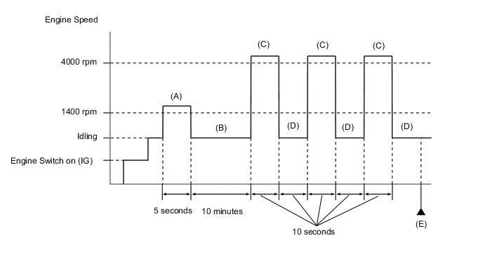
-
Connect the GTS to the DLC3.
-
Turn the engine switch on (IG) and turn the GTS on
-
Clear the DTCs (even if no DTCs are stored, perform the clear DTC procedure).
-
Turn the engine switch off and wait for at least 30 seconds.
-
Turn the engine switch on (IG) and turn the GTS on.
-
Depress the accelerator pedal until the engine speed increases to 1400 rpm or more for at least 5 seconds [A].
Tech Tips
The water control valve switches to irrigation control according to this operation.
-
Idle the engine for 10 minutes or more [B].
Tech Tips
Idle the vehicle while in irrigation control until the engine oil reaches appropriate temperature.
-
Depress the accelerator pedal until the engine speed increases to 4000 rpm for at least 10 seconds [C].
-
Idle the engine for at least 10 seconds [D].
-
Repeat step [C] and [D] 3 times or more.
-
Enter the following menus: Powertrain / Engine / Trouble Codes [E].
-
Read the pending DTCs.
Tech Tips
-
If a pending DTC is output, the system is malfunctioning.
-
If a pending DTC is not output, perform the following procedure.
-
-
Enter the following menus: Powertrain / Engine / Utility / All Readiness.
-
Input the DTC: P15E517, P15E52A or P25AE00.
-
Check the DTC judgment result.
GTS Display Description NORMAL
-
DTC judgment completed
-
System normal
ABNORMAL
-
DTC judgment completed
-
System abnormal
INCOMPLETE
-
DTC judgment not completed
-
Perform driving pattern after confirming DTC enabling conditions
Tech Tips
-
If the judgment result shows NORMAL, the system is normal.
-
If the judgment result shows ABNORMAL, the system has a malfunction.
-
If the judgment result shows INCOMPLETE, perform steps [A] through [E] again.
-
WIRING DIAGRAM
Refer to DTC P15E512 for the oil pressure sender gauge assembly circuit.
Refer to DTC P25A912 for the oil pressure switching valve assembly circuit.
CAUTION / NOTICE / HINT
Tech Tips
Read freeze frame data using the GTS. The ECM records vehicle and driving condition information as freeze frame data the moment a DTC is stored. When troubleshooting, freeze frame data can help determine if the vehicle was moving or stationary, if the engine was warmed up or not, if the air fuel ratio was lean or rich, and other data from the time the malfunction occurred.
PROCEDURE
-
CHECK ANY OTHER DTCS OUTPUT (IN ADDITION TO DTC P15E517, P15E52A OR P25AE00)
-
Connect the GTS to the DLC3.
-
Turn the engine switch on (IG).
-
Turn the GTS on.
-
Enter the following menus: Powertrain / Engine / Trouble Codes.
-
Read the DTCs.
Powertrain > Engine > Trouble CodesResult Result Proceed to DTC P15E517, P15E52A or P25AE00 is output A DTC P15E517, P15E52A or P25AE00 and other DTCs are output B
B 
GO TO DTC CHART Click here
A 
-
-
CHECK ENGINE OIL LEVEL
-
Check the engine oil level.
-
Check the state of the oil level warning light.
Result Result Proceed to Engine oil level is low and oil level warning light is illuminated A Engine oil level is within the specified range and oil level warning light is not illuminated B Tech Tips
If the oil level warning light is not illuminated even though the engine oil level is lower than the Low mark, or the oil level warning light is illuminated even though the engine oil level is within the specified range, inspect the oil level sensor and related parts for malfunctions.
B 
INSPECT OIL PRESSURE SWITCHING VALVE ASSEMBLY (OIL PRESSURE SWITCHING VALVE OPERATION) Click here
A
-
-
CHECK ENGINE OIL LEAKS
-
Check for engine oil leaks.
Result If there are engine oil leaks, perform repairs. Result Proceed to NEXT
NEXT
-
-
ADD ENGINE OIL
-
Add engine oil.
Result Proceed to NEXT
NEXT
-
-
INSPECT OIL PRESSURE SWITCHING VALVE ASSEMBLY (OIL PRESSURE SWITCHING VALVE OPERATION)
-
Connect the GTS to the DLC3.
-
Start the engine.
-
Turn the GTS on.
-
Depress the accelerator pedal until the engine speed increases to 1400 rpm or more for at least 5 seconds.
Tech Tips
The water control valve switches to irrigation control according to this operation.
-
Idle the engine for 10 minutes or more.
Tech Tips
Idle the vehicle while in irrigation control until the engine oil reaches appropriate temperature.
-
Enter the following menus: Powertrain / Engine / Utility / Engine Oil Jet Control Check.
Powertrain > Engine > UtilityTester Display Engine Oil Jet Control Check -
Compare the "Valve OFF: Hi Oil press" and "Valve ON: Low Oil press" oil pressure values in the measured results and read the difference between the oil pressure values.
OK 30 kPa (gauge) or higher Result Result Proceed to OK A NG (Oil pressure is high and does not change (200 kPa or higher)) B NG (Oil pressure is low and does not change (below 200 kPa)) C
B
INSPECT OIL PRESSURE SWITCHING VALVE ASSEMBLY Click here
C
INSPECT OIL PRESSURE SENDER GAUGE ASSEMBLY Click here
A
-
-
CLEAR DTC
-
Connect the GTS to the DLC3.
-
Turn the engine switch on (IG).
-
Turn the GTS on.
-
Clear the DTCs.
Powertrain > Engine > Clear DTCs -
Turn the engine switch off and wait for at least 30 seconds.
Result Proceed to NEXT
NEXT
-
-
CHECK WHETHER DTC OUTPUT RECURS (DTC P15E517, P15E52A OR P25AE00)
-
Drive the vehicle in accordance with the driving pattern described in Confirmation Driving Pattern.
-
Enter the following menus: Powertrain / Engine / Trouble Codes.
-
Read the Pending DTCs.
Powertrain > Engine > Trouble CodesOK DTCs are not output Result Proceed to NEXT
NEXT
END
-
-
INSPECT OIL PRESSURE SWITCHING VALVE ASSEMBLY
-
Inspect the oil pressure switching valve assembly.
Result Proceed to OK NG
NG
REPLACE OIL PRESSURE SWITCHING VALVE ASSEMBLY Click here
OK
-
-
CHECK HARNESS AND CONNECTOR (OIL PRESSURE SWITCHING VALVE ASSEMBLY - ECM)
-
Disconnect the oil pressure switching valve assembly connector.
-
Disconnect the ECM connector.
-
Measure the resistance according to the value(s) in the table below.
Standard Resistance Tester Connection Condition Specified Condition D61-1 (+B) - D1-24 (EOJ+) Always Below 1 Ω D61-2 (EOJV) - D1-25 (EOJ-) Always Below 1 Ω D61-1 (+B) or D1-24 (EOJ+) - Body ground and other terminals Always 10 kΩ or higher D61-2 (EOJV) or D1-25 (EOJ-) - Body ground and other terminals Always 10 kΩ or higher Result Proceed to OK NG
NG
REPAIR OR REPLACE HARNESS OR CONNECTOR
OK
-
-
CHECK HARNESS AND CONNECTOR (OIL PRESSURE SENDER GAUGE ASSEMBLY - ECM)
-
Disconnect the oil pressure sender gauge assembly connector.
-
Disconnect the ECM connector.
-
Measure the resistance according to the value(s) in the table below.
Standard Resistance Tester Connection Condition Specified Condition D62-1 (GND) - D1-104 (EPIM) Always Below 1 Ω D62-2 (POUT) - D1-77 (PEOJ) Always Below 1 Ω D62-3 (VC) - D1-127 (VCPM) Always Below 1 Ω D62-1 (GND) or D1-104 (EPIM) - Body ground and other terminals Always 10 kΩ or higher D62-2 (POUT) or D1-77 (PEOJ) - Body ground and other terminals Always 10 kΩ or higher D62-3 (VC) or D1-127 (VCPM) - Body ground and other terminals Always 10 kΩ or higher Result Proceed to OK NG
NG
REPAIR OR REPLACE HARNESS OR CONNECTOR
OK
-
-
INSPECT OIL PRESSURE SENDER GAUGE ASSEMBLY
-
Disconnect the oil pressure switching valve assembly connector.
-
Read the value displayed on the GTS.
-
Connect the GTS to the DLC3.
-
Start the engine.
-
Turn the GTS on.
-
Enter the following menus: Powertrain / Engine / Data List / Coolant Temperature Controlling Value and Oil Jet Pressure.
Powertrain > Engine > Data ListTester Display Coolant Temperature Controlling Value Oil Jet Pressure -
When the "Coolant Temperature Controlling Value" is 75°C to 85°C, read the "Oil Jet Pressure" at 4000 rpm.
-
-
Read the oil pressure gauge.
-
Install the oil pressure gauge.
-
Start the engine.
-
When the "Coolant Temperature Controlling Value" is 75°C to 85°C, read the oil pressure gauge at 4000 rpm.
-
-
Compare the value in the Data List using the GTS and the oil pressure gauge value in the measured results.
Standard Values match (within +/-50 kPa (gauge)) Result Proceed to OK NG
OK
REPLACE ECM Click here
NG
REPLACE OIL PRESSURE SENDER GAUGE ASSEMBLY Click here
-
-
INSPECT OIL PRESSURE SENDER GAUGE ASSEMBLY
-
Disconnect the oil pressure switching valve assembly connector.
-
Connect the GTS to the DLC3.
-
Start the engine.
-
Turn the GTS on.
-
Enter the following menus: Powertrain / Engine / Data List / Coolant Temperature Controlling Value and Oil Jet Pressure.
Powertrain > Engine > Data ListTester Display Coolant Temperature Controlling Value Oil Jet Pressure -
Read the value displayed on the GTS, when the "Coolant Temperature Controlling Value" is 75°C to 85°C, read the "Oil Jet Pressure" at 4000 rpm.
Standard 200 kPa or higher Result Proceed to OK NG
NG
INSPECT OIL PRESSURE SWITCHING VALVE ASSEMBLY Click here
OK
-
-
INSPECT OIL PRESSURE SWITCHING VALVE ASSEMBLY
-
Inspect the oil pressure switching valve assembly.
Result Proceed to OK NG
NG
REPLACE OIL PRESSURE SWITCHING VALVE ASSEMBLY Click here
OK
-
-
CHECK HARNESS AND CONNECTOR (OIL PRESSURE SWITCHING VALVE ASSEMBLY - ECM)
-
Disconnect the oil pressure switching valve assembly connector.
-
Disconnect the ECM connector.
-
Measure the resistance according to the value(s) in the table below.
Standard Resistance Tester Connection Condition Specified Condition D61-1 (+B) - D1-24 (EOJ+) Always Below 1 Ω D61-2 (EOJV) - D1-25 (EOJ-) Always Below 1 Ω D61-1 (+B) or D1-24 (EOJ+) - Body ground and other terminals Always 10 kΩ or higher D61-2 (EOJV) or D1-25 (EOJ-) - Body ground and other terminals Always 10 kΩ or higher Result Proceed to OK NG
OK
REPLACE ECM Click here
NG
REPAIR OR REPLACE HARNESS OR CONNECTOR
-
-
INSPECT OIL PRESSURE SWITCHING VALVE ASSEMBLY
-
Inspect the oil pressure switching valve assembly.
Result Proceed to OK NG
NG
REPLACE OIL PRESSURE SWITCHING VALVE ASSEMBLY Click here
OK
-
-
CHECK HARNESS AND CONNECTOR (OIL PRESSURE SENDER GAUGE ASSEMBLY - ECM)
-
Disconnect the oil pressure sender gauge assembly connector.
-
Disconnect the ECM connector.
-
Measure the resistance according to the value(s) in the table below.
Standard Resistance Tester Connection Condition Specified Condition D62-1 (GND) - D1-104 (EPIM) Always Below 1 Ω D62-2 (POUT) - D1-77 (PEOJ) Always Below 1 Ω D62-3 (VC) - D1-127 (VCPM) Always Below 1 Ω D62-1 (GND) or D1-104 (EPIM) - Body ground and other terminals Always 10 kΩ or higher D62-2 (POUT) or D1-77 (PEOJ) - Body ground and other terminals Always 10 kΩ or higher D62-3 (VC) or D1-127 (VCPM) - Body ground and other terminals Always 10 kΩ or higher Result Proceed to OK NG
NG
REPAIR OR REPLACE HARNESS OR CONNECTOR
OK
-
-
INSPECT OIL PRESSURE SENDER GAUGE ASSEMBLY
-
Disconnect the oil pressure switching valve assembly connector.
-
Read the value displayed on the GTS.
-
Connect the GTS to the DLC3.
-
Start the engine.
-
Turn the GTS on.
-
Enter the following menus: Powertrain / Engine / Data List / Coolant Temperature Controlling Value and Oil Jet Pressure.
Powertrain > Engine > Data ListTester Display Coolant Temperature Controlling Value Oil Jet Pressure -
When the "Coolant Temperature Controlling Value" is 75°C to 85°C, read the "Oil Jet Pressure" at 4000 rpm.
-
-
Read the oil pressure gauge.
-
Install the oil pressure gauge.
-
Start the engine.
-
When the "Coolant Temperature Controlling Value" is 75°C to 85°C, read the oil pressure gauge at 4000 rpm.
-
-
Compare the value in the Data List using the GTS and the oil pressure gauge value in the measured results.
Standard Values match (within +/-50 kPa (gauge)) Result Proceed to OK NG
OK
REPLACE OIL PUMP (TIMING CHAIN COVER ASSEMBLY) Click here
NG
REPLACE OIL PRESSURE SENDER GAUGE ASSEMBLY Click here
-