WIRELESS DOOR LOCK CONTROL SYSTEM(w/o Entry and Start System), Diagnostic DTC:B1242
| DTC Code | DTC Name |
|---|---|
| B1242 | Wireless Door Lock Tuner Circuit Malfunction |
DESCRIPTION
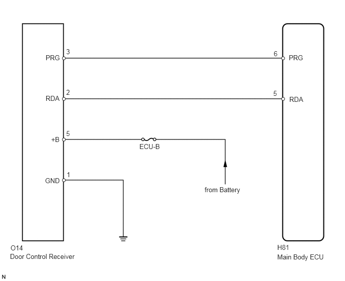
The door control receiver receives signals from the transmitter and sends these signals to the main body ECU. This DTC is stored when the applicable RDA signal cannot be received within 1 second of the PRG signal being output from the main body ECU.
DTC Code |
DTC Detection Condition |
Trouble Area |
|---|---|---|
B1242 |
The applicable RDA signal cannot be received within 1 second of the PRG signal being output from the main body ECU. |
|
WIRING DIAGRAM
CAUTION / NOTICE / HINT
Inspect the fuses for circuits related to this system before performing the following inspection procedure.
As the door control battery is installed between the vehicle battery and main body ECU (instrument panel junction block assembly), first perform the inspections in On-Vehicle Inspection to confirm that there are no malfunctions in the power source circuit for the main body ECU (instrument panel junction block assembly) before performing this troubleshooting procedure (Click here).
PROCEDURE
CLEAR DTC
Clear the DTCs (Click here).
CHECK FOR DTC
Check for DTCs (Click here).
OK
DTC B1242 is not output.
CHECK HARNESS AND CONNECTOR (MAIN BODY ECU - DOOR CONTROL RECEIVER)
-
Disconnect the H81 ECU connector.
Disconnect the O14 receiver connector.
Measure the resistance according to the value(s) in the table below.
Standard Resistance
Tester Connection
Condition
Specified Condition
H81-5 (RDA) - O14-2 (RDA)
Always
Below 1 Ω
H81-6 (PRG) - O14-3 (PRG)
H81-5 (RDA) or O14-2 (RDA) - Body ground
Always
10 kΩ or higher
H81-6 (PRG) or O14-3 (PRG) - Body ground
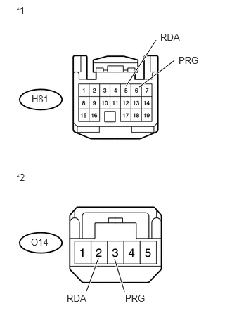
Table 1. Text in Illustration *1
Front view of wire harness connector
(to Main Body ECU)
*2
Front view of wire harness connector
(to Door Control Receiver)
REPAIR OR REPLACE HARNESS OR CONNECTOR
-
CHECK HARNESS AND CONNECTOR (DOOR CONTROL RECEIVER - BATTERY AND BODY GROUND)
-
Disconnect the O14 receiver connector.
Measure the resistance and voltage according to the value(s) in the table below.
Standard Resistance
Tester Connection
Condition
Specified Condition
O14-1 (GND) - Body ground
Always
Below 1 Ω
Standard Voltage
Tester Connection
Condition
Specified Condition
O14-5 (+B) - Body ground
Always
11 to 14 V
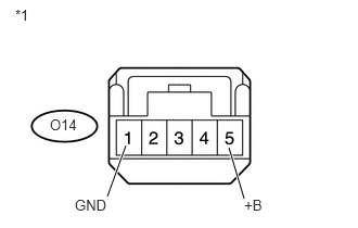
Table 2. Text in Illustration *1
Front view of wire harness connector
(to Door Control Receiver)
REPAIR OR REPLACE HARNESS OR CONNECTOR
-
REPLACE DOOR CONTROL RECEIVER
Temporarily replace the door control receiver with a new one (Click here).
Perform the registration procedures (Click here).
CLEAR DTC
Clear the DTCs (Click here).
CHECK FOR DTC
Check for DTCs (Click here).
OK
DTC B1242 is not output.
END (DOOR CONTROL RECEIVER IS DEFECTIVE)
REPLACE MAIN BODY ECU (INSTRUMENT PANEL JUNCTION BLOCK ASSEMBLY)