BRAKE CONTROL SYSTEM
-
CONSTRUCTION
-
The brake actuator assembly consists of an actuator portion, a skid control ECU, a solenoid relay, a pump motor and a master cylinder pressure sensor.
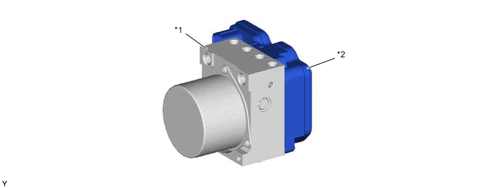
*1 Actuator Portion *2 Skid Control ECU
-
The actuator portion consists of 2 master cylinder cut solenoid valves, 4 pressure holding solenoid valves, 4 pressure reduction solenoid valves, 2 pumps, 2 reservoirs and a master cylinder pressure sensor.
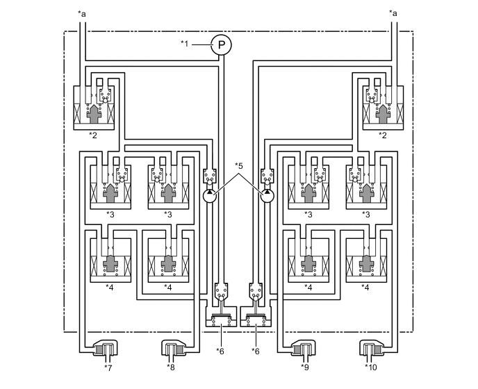
*1 Master Cylinder Pressure Sensor *2 Master Cylinder Cut Solenoid Valve *3 Pressure Holding Solenoid Valve *4 Pressure Reduction Solenoid Valve *5 Pump *6 Reservoir *7 Front Wheel Cylinder RH *8 Rear Wheel Cylinder LH *9 Rear Wheel Cylinder RH *10 Front Wheel Cylinder LH *a From Master Cylinder - -
-
-
-
OPERATION
-
ABS and EBD
-
Based on the signals received from the 4 speed sensors, the skid control ECU calculates the speed of each wheel and checks the wheel slipping conditions. In accordance with the slipping condition, the skid control ECU controls each solenoid valve in the brake actuator assembly in order to adjust the fluid pressure of each wheel cylinder in the following 3 modes: pressure increase, pressure holding and pressure reduction modes.
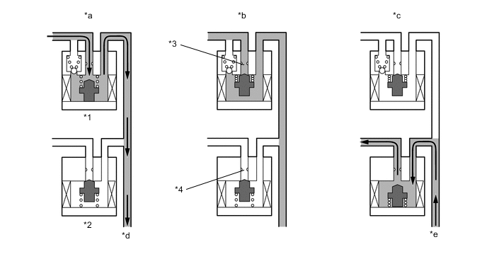
*1 Pressure Holding Solenoid Valve *2 Pressure Reduction Solenoid Valve *3 Port A *4 Port B *a Pressure Increase Mode *b Pressure Holding Mode *c Pressure Reduction Mode *d To Wheel Cylinder *e From Wheel Cylinder - - Brake Actuator Operation in ABS and EBD Pressure Mode Increase Mode Holding Mode Reduction Mode Pressure Holding Solenoid Valve (Port A) Off (Open) On (Closed) ← Pressure Reduction Solenoid Valve (Port B) Off (Closed) ← On (Open) Wheel Cylinder Pressure Increases Holds Reduces
-
-
Brake Assist
-
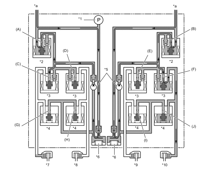
In the event of emergency braking, the skid control ECU determines the driver's intention based on the speed of the pressure increase in the master cylinder determined by the master cylinder pressure sensor signal. If the skid control ECU judges the need for additional brake assist, pressure is generated by the pump in the brake actuator assembly and directed to the wheel cylinder to apply a large amount of fluid pressure.
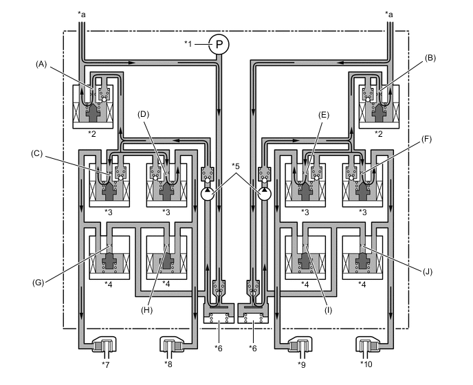
*1 Master Cylinder Pressure Sensor *2 Master Cylinder Cut Solenoid Valve *3 Pressure Holding Solenoid Valve *4 Pressure Reduction Solenoid Valve *5 Pump *6 Reservoir *7 Front Wheel Cylinder RH *8 Rear Wheel Cylinder LH *9 Rear Wheel Cylinder RH *10 Front Wheel Cylinder LH *a From Master Cylinder - - Brake Actuator Operation in Brake Assist Item Brake Assist Not Activated Brake Assist Activated Pump Off On Master Cylinder Cut Solenoid Valve Port (A) Off (Open) On* Port (B) Off (Open) On* Pressure Holding Solenoid Valve Port (C) Off (Open) ← Port (D) Off (Open) ← Port (E) Off (Open) ← Port (F) Off (Open) ← Pressure Reduction Solenoid Valve Port (G) Off (Closed) ← Port (H) Off (Closed) ← Port (I) Off (Closed) ← Port (J) Off (Closed) ← Tech Tips
*: The solenoid valve switches the hydraulic pressure between "open" and "closed" in accordance with the operating conditions by adjusting continually.
-
-
Auto LSD
-
The skid control ECU determines that the vehicle is in a state in which the Auto LSD can operate by using various sensors and switches to detect the operating conditions of the VSC OFF switch, shift position, accelerator pedal and brake pedal.
-
When the vehicle is in a state in which the Auto LSD can operate, the skid control ECU performs hydraulic pressure control of the wheel cylinder in the wheel with the faster wheel speed, so that the wheel speeds of the right and left drive wheels will become equal.
-
The Auto LSD indicator light illuminates when the vehicle is in a state in which the Auto LSD can operate, and the slip indicator light flashes during Auto LSD control.
-
If the Auto LSD function operates due to the slippage of the left drive wheel, see the next page for the operation of the solenoid valves.
Note
Use the Auto LSD only if a wheel comes off or while driving on a road surface with high driving resistance such as sand or mud. Do not use the Auto LSD for normal driving. After using the Auto LSD, make sure the Auto LSD indicator light is off before resuming driving. To operate the VSC OFF switch, make sure the wheels are not spinning.
*1 Master Cylinder Pressure Sensor *2 Master Cylinder Cut Solenoid Valve *3 Pressure Holding Solenoid Valve *4 Pressure Reduction Solenoid Valve *5 Pump *6 Reservoir *7 Front Wheel Cylinder RH *8 Rear Wheel Cylinder LH *9 Rear Wheel Cylinder RH *10 Front Wheel Cylinder LH *a From Master Cylinder - - Brake Actuator Operation in Auto LSD (Front Left Drive Wheel Slipping) Item Auto LSD Operation Not Activated Pressure Increase Mode Pressure Holding Mode Pressure Reduction Mode Pump Off On ← ← Master Cylinder Cut Solenoid Valve Port (A) Off (Open) On* ← ← Port (B) Off (Open) ← ← ← Front Brake Pressure Holding Solenoid Valve Port (C) Off (Open) On (Closed) ← ← Port (F) Off (Open) ← On (Closed) ← Pressure Reduction Solenoid Valve Port (G) Off (Closed) ← ← ← Port (J) Off (Closed) ← ← On (Open) Wheel Cylinder Pressure Right - - - - Left - Increases Holds Reduces Rear Brake Pressure Holding Solenoid Valve Port (D) Off (Open) On (Closed) ← ← Port (E) Off (Open) On (Closed) ← ← Pressure Reduction Solenoid Valve Port (H) Off (Closed) ← ← ← Port (I) Off (Closed) ← ← ← Wheel Cylinder Pressure Right - - - - Left - - - - Tech Tips
*: The solenoid valve switches the hydraulic pressure between "open" and "closed" in accordance with the operating conditions by adjusting continually.
-
-
TRC
-
The fluid pressure generated by the pump is regulated by the master cylinder cut solenoid valve to the required pressure. Thus, the wheel cylinders of the drive wheels are controlled in the following 3 modes: pressure increase, pressure holding and pressure reduction modes to control the slippage of the drive wheels. The pressure holding solenoid valve and the pressure reduction solenoid valve are turned on or off in accordance with the ABS and EBD operation patterns.
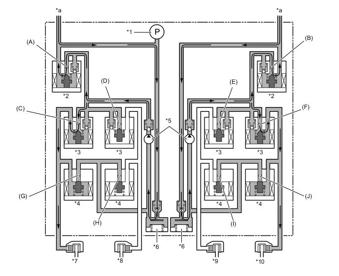
*1 Master Cylinder Pressure Sensor *2 Master Cylinder Cut Solenoid Valve *3 Pressure Holding Solenoid Valve *4 Pressure Reduction Solenoid Valve *5 Pump *6 Reservoir *7 Front Wheel Cylinder RH *8 Rear Wheel Cylinder LH *9 Rear Wheel Cylinder RH *10 Front Wheel Cylinder LH *a From Master Cylinder - - Brake Actuator Operation in TRC (2WD Models) Item TRC Operation Not Activated Pressure Increase Mode Pressure Holding Mode Pressure Reduction Mode Pump Off On ← ← Master Cylinder Cut Solenoid Valve Port (A) Off (Open) On* ← ← Port (B) Off (Open) On* ← ← Front Brake Pressure Holding Solenoid Valve Port (C) Off (Open) ← On (Closed) ← Port (F) Off (Open) ← On (Closed) ← Pressure Reduction Solenoid Valve Port (G) Off (Closed) ← ← On (Open) Port (J) Off (Closed) ← ← On (Open) Wheel Cylinder Pressure Right - Increases Holds Reduces Left - Increases Holds Reduces Rear Brake Pressure Holding Solenoid Valve Port (D) Off (Open) On (Closed) ← ← Port (E) Off (Open) On (Closed) ← ← Pressure Reduction Solenoid Valve Port (H) Off (Closed) ← ← ← Port (I) Off (Closed) ← ← ← Wheel Cylinder Pressure Right - - - - Left - - - - Tech Tips
*: The solenoid valve switches the hydraulic pressure between "open" and "closed" in accordance with the operating conditions by adjusting continually.

*1 Master Cylinder Pressure Sensor *2 Master Cylinder Cut Solenoid Valve *3 Pressure Holding Solenoid Valve *4 Pressure Reduction Solenoid Valve *5 Pump *6 Reservoir *7 Front Wheel Cylinder RH *8 Rear Wheel Cylinder LH *9 Rear Wheel Cylinder RH *10 Front Wheel Cylinder LH *a From Master Cylinder - - Brake Actuator Operation in TRC (4WD/AWD Models) Item TRC Operation Not Activated Pressure Increase Mode Pressure Holding Mode Pressure Reduction Mode Pump Off On ← ← Master Cylinder Cut Solenoid Valve Port (A) Off (Open) On* ← ← Port (B) Off (Open) On* ← ← Front Brake Pressure Holding Solenoid Valve Port (C) Off (Open) ← On (Closed) ← Port (F) Off (Open) ← On (Closed) ← Pressure Reduction Solenoid Valve Port (G) Off (Closed) ← ← On (Open) Port (J) Off (Closed) ← ← On (Open) Wheel Cylinder Pressure Right - Increases Holds Reduces Left - Increases Holds Reduces Rear Brake Pressure Holding Solenoid Valve Port (D) Off (Open) ← On (Closed) ← Port (E) Off (Open) ← On (Closed) ← Pressure Reduction Solenoid Valve Port (H) Off (Closed) ← ← On (Open) Port (I) Off (Closed) ← ← On (Open) Wheel Cylinder Pressure Right - Increases Holds Reduces Left - Increases Holds Reduces Tech Tips
*: The solenoid valve switches the hydraulic pressure between "open" and "closed" in accordance with the operating conditions by adjusting continually.
-
-
VSC
-
The VSC, by way of the solenoid valves, controls the fluid pressure generated by the pump and applies it to the brake wheel cylinder of each wheel in the following 3 modes: pressure increase, pressure holding and pressure reduction modes. As a result, the tendency for front wheel skid or rear wheel skid is controlled.
-
In the front wheel skid restraining control, the brakes of the front wheels and the brake of the rear wheel on the inner circle of the turn are applied. Also, depending on whether the brake is on or off and also depending on the vehicle conditions, there are circumstances in which the brake might not be applied to the wheels even if the wheel is targeted for braking. The following diagram shows the hydraulic circuit in the pressure increase mode, as it controls the front wheel skid condition while the vehicle makes a right turn. In other operating modes, the pressure holding valve and the pressure reduction valve are turned on or off in accordance with the ABS and EBD operation patterns.
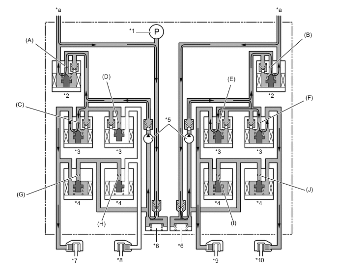
*1 Master Cylinder Pressure Sensor *2 Master Cylinder Cut Solenoid Valve *3 Pressure Holding Solenoid Valve *4 Pressure Reduction Solenoid Valve *5 Pump *6 Reservoir *7 Front Wheel Cylinder RH *8 Rear Wheel Cylinder LH *9 Rear Wheel Cylinder RH *10 Front Wheel Cylinder LH *a From Master Cylinder - - Brake Actuator Operation in VSC (Front Wheel Skid Restraining) Item VSC Operation Not Activated Pressure Increase Mode Pressure Holding Mode Pressure Reduction Mode Pump Off On ← ← Master Cylinder Cut Solenoid Valve Port (A) Off (Open) On* ← ← Port (B) Off (Open) On* ← ← Front Brake Pressure Holding Solenoid Valve Port (C) Off (Open) ← On (Closed) ← Port (F) Off (Open) ← On (Closed) ← Pressure Reduction Solenoid Valve Port (G) Off (Closed) ← ← On (Open) Port (J) Off (Closed) ← ← On (Open) Wheel Cylinder Pressure Right - Increases Holds Reduces Left - Increases Holds Reduces Rear Brake Pressure Holding Solenoid Valve Port (D) Off (Open) On (Closed) ← ← Port (E) Off (Open) ← On (Closed) ← Pressure Reduction Solenoid Valve Port (H) Off (Closed) ← ← ← Port (I) Off (Closed) ← ← On (Open) Wheel Cylinder Pressure Right - Increases Holds Reduces Left - - - - Tech Tips
*: The solenoid valve switches the hydraulic pressure between "open" and "closed" in accordance with the operating conditions by adjusting continually.
-
In the rear wheel skid restraining control, the brake of the wheels on the outer circle of the turn is applied. Also, depending on whether the brake is on or off and also depending on the vehicle conditions, there are circumstances in which the brake might not be applied to the wheels even if the wheel is targeted for braking. The following diagram shows the hydraulic circuit in pressure increase mode, as it controls the rear wheel skid condition while the vehicle makes a right turn. In other operating modes, the pressure holding valve and the pressure reduction valve are turned on or off in accordance with the ABS and EBD operation patterns.
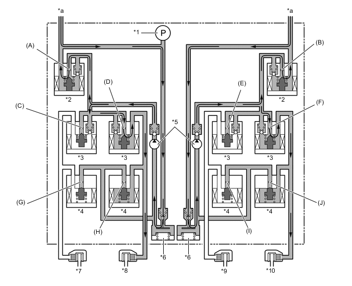
*1 Master Cylinder Pressure Sensor *2 Master Cylinder Cut Solenoid Valve *3 Pressure Holding Solenoid Valve *4 Pressure Reduction Solenoid Valve *5 Pump *6 Reservoir *7 Front Wheel Cylinder RH *8 Rear Wheel Cylinder LH *9 Rear Wheel Cylinder RH *10 Front Wheel Cylinder LH *a From Master Cylinder - - Brake Actuator Operation in VSC (Rear Wheel Skid Restraining) Item VSC Operation Not Activated Pressure Increase Mode Pressure Holding Mode Pressure Reduction Mode Pump Off On ← ← Master Cylinder Cut Solenoid Valve Port (A) Off (Open) On* ← ← Port (B) Off (Open) On* ← ← Front Brake Pressure Holding Solenoid Valve Port (C) Off (Open) On (Closed) ← ← Port (F) Off (Open) ← On (Closed) ← Pressure Reduction Solenoid Valve Port (G) Off (Closed) ← ← ← Port (J) Off (Closed) ← ← On (Open) Wheel Cylinder Pressure Right - - - - Left - Increases Holds Reduces Rear Brake Pressure Holding Solenoid Valve Port (D) Off (Open) ← On (Closed) ← Port (E) Off (Open) On (Closed) ← ← Pressure Reduction Solenoid Valve Port (H) Off (Closed) ← ← On (Open) Port (I) Off (Closed) ← ← ← Wheel Cylinder Pressure Right - - - - Left - Increases Holds Reduces Tech Tips
*: The solenoid valve switches the hydraulic pressure between "open" and "closed" in accordance with the operating conditions by adjusting continually.
-
-
Cooperative Control
-
The operation of the solenoid valves under the cooperative control is the same as the TRC or VSC operation.
-
-
Hill-start Assist Control
-
Hill-start assist control operation is performed by closing the master cylinder cut solenoid valves after the driver operates the brake pedal and leaving a certain amount of hydraulic pressure created by the pump in the wheel cylinder. The diagram below shows the hydraulic circuit in the pressure holding mode:
*1 Master Cylinder Pressure Sensor *2 Master Cylinder Cut Solenoid Valve *3 Pressure Holding Solenoid Valve *4 Pressure Reduction Solenoid Valve *5 Pump *6 Reservoir *7 Front Wheel Cylinder RH *8 Rear Wheel Cylinder LH *9 Rear Wheel Cylinder RH *10 Front Wheel Cylinder LH *a From Master Cylinder - - Brake Actuator Operation in Hill-start Assist Control Item Hill-start Assist Control Operation Not Activated Pressure Holding Mode Pressure Reduction Mode Pump Off On ← Master Cylinder Cut Solenoid Valve Port (A) Off (Open) On Off (Open) Port (B) Off (Open) On Off (Open) Front Brake Pressure Holding Solenoid Valve Port (C) Off (Open) ← ← Port (F) Off (Open) ← ← Pressure Reduction Solenoid Valve Port (G) Off (Closed) ← ← Port (J) Off (Closed) ← ← Wheel Cylinder Pressure Right - Holds Reduces Left - Holds Reduces Rear Brake Pressure Holding Solenoid Valve Port (D) Off (Open) ← ← Port (E) Off (Open) ← ← Pressure Reduction Solenoid Valve Port (H) Off (Closed) ← ← Port (I) Off (Closed) ← ← Wheel Cylinder Pressure Right - Holds Reduces Left - Holds Reduces
-
-
Downhill Assist Control
-
Based on the information provided by various sensors, switches and the ECM, the skid control ECU determines the conditions that enable the downhill assist control operation. Then, the skid control ECU controls the fluid pressure that is generated by the pump and applies it by way of the solenoid valve to the brake wheel cylinder of each wheel in the following 3 modes: pressure reduction, pressure holding and pressure increase modes.
-
The skid control ECU computes the vehicle speed, travel direction and the gradient of the hill in accordance with the signals that are input by the speed sensor and the yaw rate and deceleration sensor, and performs brake control to attain the target vehicle speed. The target vehicle speed is determined by the direction of the vehicle.
Travel Direction Target Vehicle Speed Forward 5 km/h to 7 km/h (3 mph to 4 mph) Backward 3 km/h to 5 km/h (2 mph to 3 mph) -
During the downhill assist control operation, the skid control ECU outputs signals to the stop light control relay assembly to cause the stop light to turn on and to the combination meter assembly to cause the slip indicator light to blink.
-
The downhill assist control does not operate under the conditions described below even if the downhill assist control switch is turned on. In this case, the downhill assist control indicator light blinks to alert the driver.
-
The shift range is in a position other than M1*1, S1*2 or R.
-
*1: Except models with 2AR-FE engines
-
*2: Models with 2AR-FE engines
-
A malfunction occurs in the downhill assist control system.
-
The temperature of the brake actuator rises, causing the downhill assist control operation to stop.
-
-
Under the conditions described below, the downhill assist control operates. However, the downhill assist control indicator light blinks to alert the driver.
-
The shift lever is in N.
-
If the downhill assist control switch is turned off during the downhill assist control operation, the hydraulic pressure decreases gradually to stop the downhill assist control operation.
*1 Master Cylinder Pressure Sensor *2 Master Cylinder Cut Solenoid Valve *3 Pressure Holding Solenoid Valve *4 Pressure Reduction Solenoid Valve *5 Pump *6 Reservoir *7 Front Left Wheel Cylinder RH *8 Rear Wheel Cylinder LH *9 Rear Left Wheel Cylinder RH *10 Front Wheel Cylinder LH *a From Master Cylinder - - Brake Actuator Operation in Downhill Assist Control Item Downhill Assist Control Operation Not Activated Pressure Increase Mode Pressure Holding Mode Pressure Reduction Mode Pump Off On ← ← Master Cylinder Cut Solenoid Valve Port (A) Off (Open) On* ← ← Port (B) Off (Open) On* ← ← Front Brake Pressure Holding Solenoid Valve Port (C) Off (Open) ← On (Closed) ← Port (F) Off (Open) ← On (Closed) ← Pressure Reduction Solenoid Valve Port (G) Off (Closed) ← ← On (Open) Port (J) Off (Closed) ← ← On (Open) Wheel Cylinder Pressure Right - Increases Holds Reduces Left - Increases Holds Reduces Rear Brake Pressure Holding Solenoid Valve Port (D) Off (Open) ← On (Closed) ← Port (E) Off (Open) ← On (Closed) ← Pressure Reduction Solenoid Valve Port (H) Off (Closed) ← ← On (Open) Port (I) Off (Closed) ← ← On (Open) Wheel Cylinder Pressure Right - Increases Holds Reduces Left - Increases Holds Reduces Tech Tips
*: The solenoid valve switches the hydraulic pressure between "open" and "closed" in accordance with the operating conditions by adjusting continually.
-
-
-