SEAT BELT WARNING SYSTEM(w/o Occupant Classification System) Rear Seat Belt Warning Light Malfunction
| DTC Code | DTC Name |
|---|---|
| Rear Seat Belt Warning Light Malfunction |
DESCRIPTION
When a rear door is opened and closed (the rear door courtesy light switch turns on and off) with the power switch on (IG), or when a rear door is opened and closed (the rear door courtesy light switch turns on and off) and then the power switch is turned on (IG), the rear seat belt warning light in the combination meter assembly turns on to inform the driver of condition of the rear seat belts. If a rear seat belt is fastened or unfastened, the warning light changes to indicate the current condition of the rear seat belts.
Only for vehicles with a rear seat belt indicator.
WIRING DIAGRAM
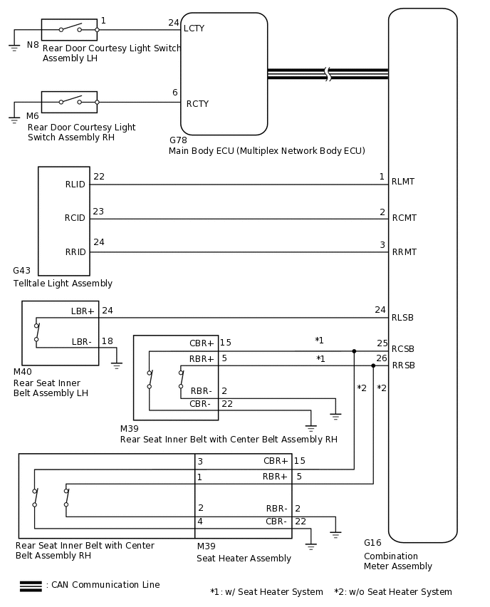
CAUTION / NOTICE / HINT
The seat belt warning system uses a CAN communication system. Inspect the communication function by following How to Proceed with troubleshooting.
for LHD:Click here
for RHD:Click here
When replacing the main body ECU (multiplex network body ECU), make sure to replace it with a new one.
PROCEDURE
READ VALUE USING GTS (RL DOOR COURTESY SW, RR DOOR COURTESY SW)
Connect the GTS to the DLC3.
Turn the power switch on (IG).
Turn the GTS on.
Enter the following menus: Body Electrical / Main Body / Data List.
Read the Data List according to the display on the GTS.
Body Electrical > Main Body > Data List
Tester Display
Measurement Item
Range
Normal Condition
Diagnostic Note
RR Door Courtesy SW
Rear door LH courtesy light switch signal
ON/OFF
ON: Rear door LH open
OFF: Rear door LH closed
-
RL Door Courtesy SW
Rear door RH courtesy light switch signal
ON/OFF
ON: Rear door RH open
OFF: Rear door RH closed
-
Body Electrical > Main Body > Data List
Tester Display
RR Door Courtesy SW
RL Door Courtesy SW
Result
Result
Proceed to
ON or OFF is displayed on the GTS screen according to the rear door courtesy light switch condition
A
ON or OFF is not displayed normally on the GTS screen according to the rear door courtesy light switch condition
B
READ VALUE USING GTS (2ND-ROW SEATBELT BUCKLE [R], 2ND-ROW SEATBELT BUCKLE [L], 2ND-ROW SEATBELT BUCKLE [C])
Connect the GTS to the DLC3.
Turn the power switch on (IG).
Turn the GTS on.
Enter the following menus: Body Electrical / Combination Meter / Data List.
Read the Data List according to the display on the GTS.
Body Electrical > Combination Meter > Data List
Tester Display
Measurement Item
Range
Normal Condition
Diagnostic Note
2nd-Row Seatbelt Buckle (R)
Rear seat belt buckle RH signal
ON/OFF
ON: Rear seat belt RH fastened
OFF: Rear seat belt RH unfastened
-
2nd-Row Seatbelt Buckle (L)
Rear seat belt buckle LH signal
ON/OFF
ON: Rear seat belt LH fastened
OFF: Rear seat belt LH unfastened
-
2nd-Row Seatbelt Buckle (C)
Rear seat center belt buckle signal
ON/OFF
ON: Rear seat center belt fastened
OFF: Rear seat center belt unfastened
-
Body Electrical > Combination Meter > Data List
Tester Display
2nd-Row Seatbelt Buckle (R)
2nd-Row Seatbelt Buckle (L)
2nd-Row Seatbelt Buckle (C)
Result
Result
Proceed to
ON or OFF is displayed on the GTS screen according to the rear seat belt condition
A
ON or OFF is not displayed normally on the GTS screen according to the rear seat belt condition (w/o Seat Heater System)
B
ON or OFF is not displayed normally on the GTS screen according to the rear seat belt condition (w/ Seat Heater System)
C
PERFORM ACTIVE TEST USING GTS (REAR SEAT BELT)
Connect the GTS to the DLC3.
Turn the power switch on (IG).
Turn the GTS on.
Enter the following menus: Body Electrical / Combination Meter / Data List.
Read the Data List according to the display on the GTS.
Body Electrical > Combination Meter > Active Test
Tester Display
Measurement Item
Control Range
Diagnostic Note
Rear Seat Belt
Rear seat belt warning light
ON/OFF
Confirm that the vehicle is stopped.
Body Electrical > Combination Meter > Active Test
Tester Display
Rear Seat Belt
OK
The rear seat belt warning light on the combination meter assembly operates normally.
Result
Proceed to
OK
NG
NG INSPECT TELLTALE LIGHT ASSEMBLYClick here
REPLACE COMBINATION METER ASSEMBLY
Replace the combination meter assembly with a new one.
Result
Proceed to
NEXT
CHECK REAR SEAT BELT WARNING LIGHT
Check the operation of the rear seat belt warning light.
Result
Proceed to
The rear seat belt warning light operates normally.
The rear seat belt warning light operates abnormally.
The rear seat belt warning light operates normally. REPLACE MAIN BODY ECU (MULTIPLEX NETWORK BODY ECU)
Click here(for LHD)
Click here(for RHD)
The rear seat belt warning light operates abnormally. END (COMBINATION METER ASSEMBLY WAS DEFECTIVE)
INSPECT TELLTALE LIGHT ASSEMBLY
Remove the telltale light assembly.
Inspect the telltale light assembly.
Result
Proceed to
OK
NG
CHECK HARNESS AND CONNECTOR (TELLTALE LIGHT ASSEMBLY - COMBINATION METER ASSEMBLY AND BODY GROUND)
Disconnect the G43 telltale light assembly connector.
Disconnect the G16 combination meter assembly meter connector.
Measure the resistance according to the value(s) in the table below.
Standard Resistance
Tester Connection
Condition
Specified Condition
G43-22 (RLID) - G16-1 (RLMT)
Always
Below 1 Ω
G43-23 (RCID) - G16-2 (RCMT)
G43-24 (RRID) - G16-3 (RRMT)
G43-22 (RLID) - Body ground
Always
10 kΩ or higher
G43-23 (RCID) - Body ground
G43-24 (RRID) - Body ground
Result
Proceed to
OK
NG
NG REPAIR OR REPLACE HARNESS OR CONNECTOR
INSPECT REAR SEAT INNER BELT ASSEMBLY
Remove the rear seat inner belt assembly.
Inspect the rear seat inner belt assembly.
Result
Proceed to
OK
NG (for LH)
NG (for RH or for Center)
CHECK HARNESS AND CONNECTOR (REAR SEAT INNER BELT ASSEMBLY - COMBINATION METER ASSEMBLY AND BODY GROUND)
Disconnect the M40*1 or M39*2 rear seat inner belt with center belt assembly connector.
*1: for LH
*2: for Center or for RH
Disconnect the G16 combination meter assembly connector.
Measure the resistance according to the value(s) in the table below.
Standard Resistance
for LH
Tester Connection
Condition
Specified Condition
M40-24 (LBR+) - G16-24 (RLSB)
Always
Below 1 Ω
M40-18 (LBR-) - Body ground
M40-24 (LBR+) - Body ground
Always
10 kΩ or higher
for Center
Tester Connection
Condition
Specified Condition
M39-15 (CBR+) - G16-25 (RCSB)
Always
Below 1 Ω
M39-22 (CBR-) - Body ground
M39-15 (CBR+) - Body ground
Always
10 kΩ or higher
for RH
Tester Connection
Condition
Specified Condition
M39-5 (RBR+) - G16-26 (RRSB)
Always
Below 1 Ω
M39-2 (RBR-) - Body ground
M39-5 (RBR+) - Body ground
Always
10 kΩ or higher
Result
Proceed to
OK
NG
NG REPAIR OR REPLACE HARNESS OR CONNECTOR
INSPECT REAR SEAT INNER BELT ASSEMBLY
Remove the rear seat inner belt assembly.
Inspect the rear seat inner belt assembly.
Result
Proceed to
OK (for LH)
OK (for RH or for Center)
NG (for LH)
NG (for RH or for Center)
OK (for RH or for Center) INSPECT SEAT HEATER ASSEMBLYClick here
CHECK HARNESS AND CONNECTOR (REAR SEAT INNER BELT ASSEMBLY LH - COMBINATION METER ASSEMBLY AND BODY GROUND)
Disconnect the M40 rear seat inner belt with center belt assembly LH connector.
Disconnect the G16 combination meter assembly connector.
Measure the resistance according to the value(s) in the table below.
Standard Resistance
Tester Connection
Condition
Specified Condition
M40-24 (LBR+) - G16-24 (RLSB)
Always
Below 1 Ω
M40-18 (LBR-) - Body ground
M40-13 (LBR+) - Body ground
Always
10 kΩ or higher
Result
Proceed to
OK
NG
NG REPAIR OR REPLACE HARNESS OR CONNECTOR
INSPECT SEAT HEATER ASSEMBLY
-
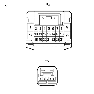
*a
Connector A
*b
Connector B
*c
Component without harness connected
(Seat Heater Assembly)
Remove the seat heater assembly.
Measure the resistance according to the value(s) in the table below.
Standard Resistance
Tester Connection
Condition
Specified Condition
A-15 (CBR+) - B-3
Always
Below 1 Ω
A-22 (CBR-) - B-4
A-5 (BBR+) - B-1
A-2 (BBR-) - B-2
Result
Proceed to
OK
NG
-
CHECK HARNESS AND CONNECTOR (SEAT HEATER ASSEMBLY - COMBINATION METER ASSEMBLY AND BODY GROUND)
Disconnect the M39 seat heater assembly connector.
Disconnect the G16 combination meter assembly connector.
Measure the resistance according to the value(s) in the table below.
Standard Resistance
for Center
Tester Connection
Condition
Specified Condition
M39-15 (CBR+) - G16-25 (RCSB)
Always
Below 1 Ω
M39-22 (CBR-) - Body ground
M39-15 (CBR+) - Body ground
Always
10 kΩ or higher
for RH
Tester Connection
Condition
Specified Condition
M39-5 (RBR+) - G16-26 (RRSB)
Always
Below 1 Ω
M39-2 (RBR-) - Body ground
M39-5 (RBR+) - Body ground
Always
10 kΩ or higher
Result
Proceed to
OK
NG
NG REPAIR OR REPLACE HARNESS OR CONNECTOR