ДВИГАТЕЛЬ В СБОРЕ УСТАНОВКА
-
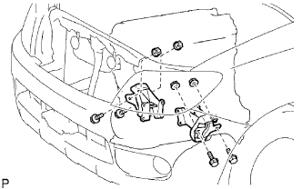
INSTALL FRONT ENGINE MOUNTING BRACKET LH
-
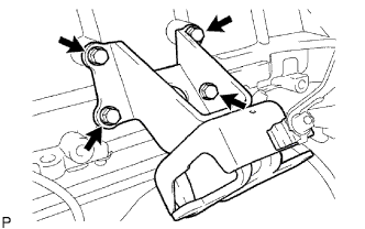
Install the mounting bracket with the 4 bolts.
- Torque:
- 51 N*m { 520 kgf*cm, 38 ft.*lbf }
-
-
INSTALL FRONT ENGINE MOUNTING BRACKET RH
-
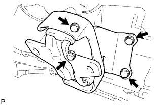
Install the mounting bracket with the 4 bolts.
- Torque:
- 51 N*m { 520 kgf*cm, 38 ft.*lbf }
-
-
INSTALL CAMSHAFT TIMING OIL CONTROL VALVE
-
Apply a coat of engine oil to a new O-ring.
-
Install the O-ring to the oil control valve.
-
Install the oil control valve with the bolt.
- Torque:
- 8.0 N*m { 82 kgf*cm, 71 in.*lbf }
-
-
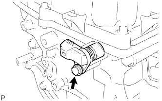
INSTALL CRANKSHAFT POSITION SENSOR
-
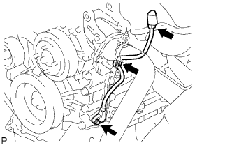
Apply a light coat of engine oil to the O-ring of the sensor.
-
Install the sensor with the bolt.
- Torque:
- 8.5 N*m { 87 kgf*cm, 75 in.*lbf }
-
Install the connector to the connector bracket.
-
Attach the harness clamp.
-
Connect the sensor connector.
-
-
INSTALL CAMSHAFT POSITION SENSOR
-
Apply a coat of engine oil to a new O-ring.
-
Install the O-ring to the sensor.
-
Install the sensor with the bolt.
- Torque:
- 8.5 N*m { 87 kgf*cm, 75 in.*lbf }
-
-
INSTALL ENGINE COOLANT TEMPERATURE SENSOR
-
Using a 19 mm deep socket wrench, install a new gasket and the sensor.
-
-
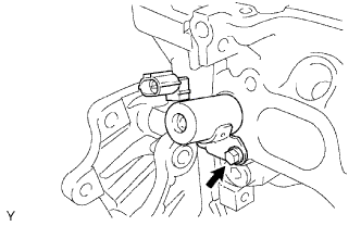
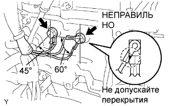
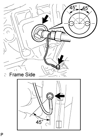
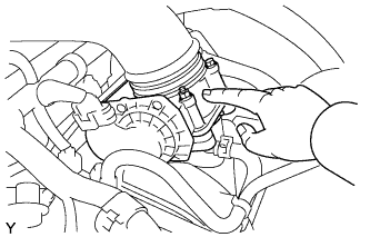
INSTALL KNOCK SENSOR
-
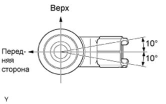
Install the sensor so that it is horizontal as shown in the illustration. Then install the bolt.
- Torque:
- 20 N*m { 204 kgf*cm, 15 ft.*lbf }
Tech Tips
It is acceptable for the sensor to be tilted +-10°.
-
Connect the sensor connector.
-
-
INSTALL NO. 1 WATER BY-PASS PIPE
-
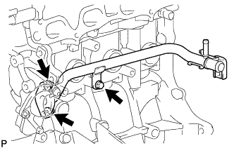
Install a new gasket and the water by-pass pipe with the 2 nuts and bolt.
- Torque:
- 17.5 N*m { 178 kgf*cm, 13 ft.*lbf }
-
-
INSTALL OIL PRESSURE SWITCH
-
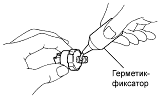
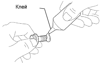
Apply adhesive to 2 or 3 threads of the oil pressure switch.
Adhesive Toyota Genuine Adhesive 1344, Three Bond 1344 or equivalent -
Install the oil pressure switch.
- Torque:
- 15 N*m { 153 kgf*cm, 11 ft.*lbf }
Note
Do not start the engine for at least 1 hour after installation of the switch.
-
Connect the oil pressure switch connector.
-
Start the engine and check for engine oil leaks.
-
-
INSTALL NO. 1 IDLER PULLEY
-
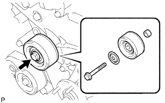
Install the spacer, idler pulley and pulley plate with the bolt.
- Torque:
- 43 N*m { 439 kgf*cm, 32 ft.*lbf }
-
-
INSTALL THERMOSTAT
-
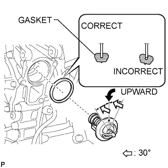
Install a new gasket to the thermostat.
Tech Tips
When installing the thermostat to the gasket, be careful not to deform the gasket. Make sure that the thermostat is properly installed into the groove of the gasket, as shown in the illustration.
-
Insert the thermostat into the cylinder block with the jiggle valve facing straight upward.
Tech Tips
The jiggle valve may be set within 10°of either side of the prescribed position.
-
-
INSTALL WATER INLET
-
Install the inlet with the 2 nuts and bolt.
- Torque:
- 20 N*m { 204 kgf*cm, 15 ft.*lbf }
-
Connect the connector.
-
-
INSTALL V-RIBBED BELT TENSIONER
-
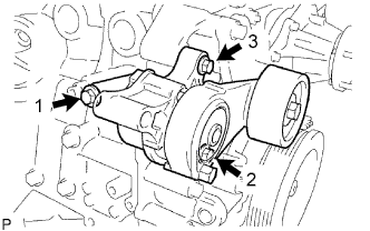
Temporarily install the belt tensioner with the 3 bolts.
Tech Tips
Make sure the flanges of the bolts are contacting the tensioner surface.
-
Install the tensioner by tightening the 3 bolts in the order shown in the illustration.
- Torque:
- 40 N*m { 408 kgf*cm, 30 ft.*lbf, for bolt 1 }
- 21 N*m { 214 kgf*cm, 15 ft.*lbf, for bolt 2 }
- 43 N*m { 438 kgf*cm, 32 ft.*lbf, for bolt 3 }
-
-
INSTALL NO. 1 COMPRESSOR MOUNTING BRACKET (w/ Air Conditioning System)
Note
Install the No. 1 compressor mounting bracket exactly as described in the procedures below to properly secure and prevent damage to the fan and generator V belt.
-
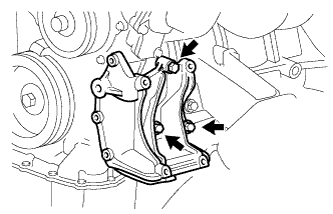
Temporarily install the No. 1 compressor mounting bracket with the 3 bolts.
Tech Tips
Temporarily install the No. 1 compressor mounting bracket with the 3 bolts so that the bracket can be moved by hand.
-
Push the No. 1 compressor mounting bracket toward the cylinder block as shown in the illustration and tighten the bolt B.
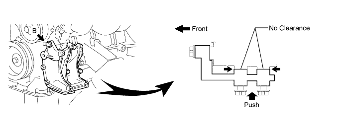
- Torque:
- 45 N*m { 459 kgf*cm, 33 ft.*lbf, for bolt B }
Tech Tips
Make sure there is no clearance between the cylinder block and No. 1 compressor mounting bracket as shown in the illustration.
-
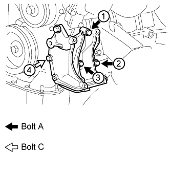
Uniformly tighten the 4 bolts in the order shown in the illustration.
- Torque:
- 45 N*m { 459 kgf*cm, 33 ft.*lbf, for bolt A }
- 24.5 N*m { 250 kgf*cm, 18 ft.*lbf, for bolt C }
-
-
INSTALL IDLE PULLEY ASSEMBLY (w/ Air Conditioning System)
-
Temporarily install the idle pulley assembly with the bolt.
Note
Do not use any tools.
-
Tighten the bolt.
- Torque:
- 44 N*m { 449 kgf*cm, 32 ft.*lbf }
-
-
INSTALL EXHAUST MANIFOLD
-
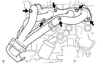
Install a new gasket and the exhaust manifold with the 6 nuts.
- Torque:
- 36 N*m { 367 kgf*cm, 27 ft.*lbf }
-
-
INSTALL EXHAUST MANIFOLD HEAT INSULATOR
-
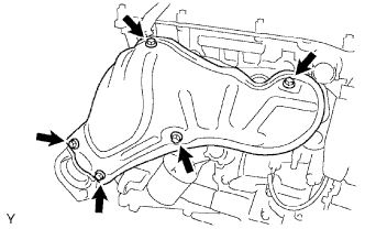
Install the heat insulator with the 5 bolts.
- Torque:
- 12 N*m { 122 kgf*cm, 9 ft.*lbf }
-
-
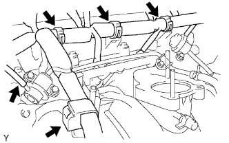
INSTALL INTAKE MANIFOLD
-
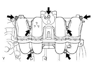
Install a new gasket and the intake manifold with the 5 bolts and 2 nuts.
- Torque:
- 25 N*m { 255 kgf*cm, 18 ft.*lbf }
-
Connect the crankshaft position sensor to the clamp.
-
-
INSTALL INJECTOR
-
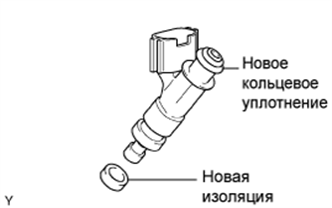
Install a new insulator to the injector.
-
Apply a light coat of grease or gasoline to a new O-ring and install it to the injector.
-
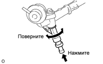
Apply a light coat of grease or gasoline on the place where the delivery pipe touches the O-ring.
-
To install the fuel injector into the fuel delivery pipe, push the fuel injector while twisting it back and forth.
Note
-
Be careful not to twist the O-ring.
-
After installing the fuel injector, check that it turns smoothly. If not, reinstall it with a new O-ring.
-
-
Position the injector connector so that it faces downward.
-
-
INSTALL FUEL DELIVERY PIPE
-
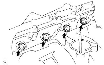
Install the 4 spacers to the cylinder head.
-
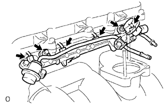
Install the delivery pipe together with the 4 injectors and 4 spacers with the 2 bolts.
- Torque:
- 12 N*m { 122 kgf*cm, 9 ft.*lbf }
-
Connect the 4 injector connectors.
-
Connect the 4 clamps and wire harness to the delivery pipe.
-
Connect the vacuum hose.
-
-
INSTALL THROTTLE BODY
-
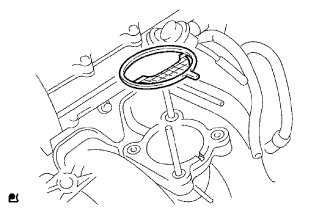
Install a new gasket on the intake manifold.
Tech Tips
Align the protrusion of the gasket with the groove of the intake manifold.
-
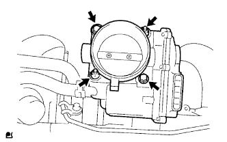
Install the throttle body with the 2 bolts and 2 nuts.
- Torque:
- 9.0 N*m { 92 kgf*cm, 80 in.*lbf }
-
Connect the 2 water by-pass hoses to the throttle body.
-
Connect the throttle position sensor and control motor connector.
-
-
INSTALL ENGINE WIRE
-
Connect the wire harness (engine ground wire) to the engine rear side with the 2 bolts so that it is within the specified range shown in the illustration.
- Torque:
- 31 N*m { 316 kgf*cm, 23 ft.*lbf }
-
Connect the oil pressure sensor connector.
-
Connect the noise filter connector.
-
Connect the camshaft position sensor connector.
-
Connect the 4 injector connectors.
-
Connect the crankshaft position sensor connector.
-
Connect the OCV connector.
-
Connect the VSV for EVAP connector.
-
Connect the throttle body connector.
-
Connect the ECT sensor connector.
-
Connect the knock sensor connector.
-
Connect the wire harness to the clamps.
-
-
INSTALL GENERATOR
-
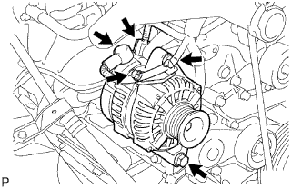
Install the generator with the 2 bolts.
- Torque:
- 43 N*m { 438 kgf*cm, 32 ft.*lbf }
-
Install the generator wire with the bolt and nut.
- Torque:
- 9.8 N*m { 100 kgf*cm, 87 in.*lbf }
-
Connect the connector.
-
-
INSTALL VENTILATION PIPE
-
Install the ventilation pipe with the bolt.
- Torque:
- 18 N*m { 184 kgf*cm, 13 ft.*lbf }
-
-
INSTALL SPARK PLUG
-
INSTALL IGNITION COIL
-
Install the ignition coil with the bolt.
- Torque:
- 9.0 N*m { 92 kgf*cm, 80 in.*lbf }
-
Connect the 4 ignition coil connectors.
-
-
REMOVE ENGINE FROM ENGINE STAND
-
INSTALL ENGINE ASSEMBLY
-
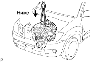
Attach the engine sling device and chain block to the engine hangers.
-
Slowly lower the engine assembly into the engine compartment.
-
Install the engine mounting brackets with the 4 bolts and 4 nuts.
- Torque:
- 38 N*m { 388 kgf*cm, 28 ft.*lbf }
-
-
INSTALL REAR END PLATE
-
Install the end plate with the 2 bolts.
- Torque:
- 18 N*m { 184 kgf*cm, 13 ft.*lbf }
-
-
INSTALL FLYWHEEL
Tech Tips
-
The mounting bolts are tightened in 2 progressive steps.
-
If any of the mounting bolts is broken or deformed, replace it.
-
Apply adhesive to 2 or 3 threads of the mounting bolt end.
Adhesive Toyota Genuine Adhesive 1324, Three Bond 1324 or equivalent -
Install the flywheel.
-
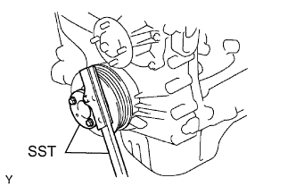
Fix the crankshaft in place with SST.
- SST
- 09213-54015 ( 91651-60855 )
- 09330-00021
-
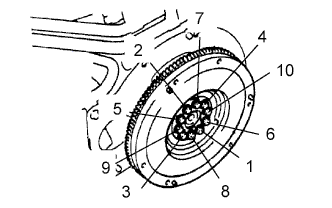
Install and uniformly tighten the 10 mounting bolts in several passes in the order shown in the illustration.
- Torque:
- 26.5 N*m { 270 kgf*cm, 20 ft.*lbf }
If any of the mounting bolts does not meet the torque specification, replace the mounting bolts.
-
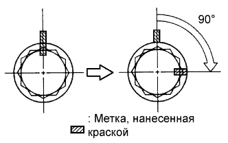
Mark the mounting bolts with paint.
-
Retighten the mounting bolts by 90° in the numerical order shown in the illustration.
-
Check that the painted marks are now at a 90° angle to the position.
-
-
INSTALL CLUTCH DISC
-
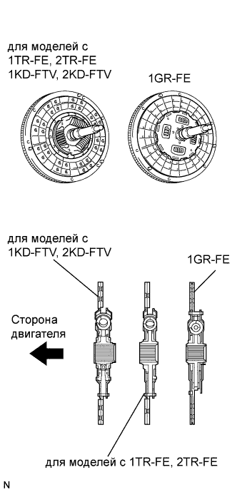
Вставьте SST в ведомый диск сцепления. Затем вставьте SST (вместе с ведомым диском сцепления) в маховик.
- SST
- 09301-00110
Note
Следите за тем, чтобы ведомый диск сцепления был вставлен правильной стороной.
-
-
INSTALL CLUTCH COVER
-
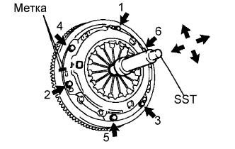
Совместите сборочные метки кожуха сцепления и маховика.
-
Затяните 6 болтов, как рассмотрено ниже.
-
Первым следует затягивать болт, который находится ближе всех к штифту.
-
Равномерно затяните 6 болтов, выбирая диаметрально противоположные пары относительно положения первого болта. Используйте для справки рисунок.
- Torque:
- 19 Н*м { 195 кгс*см, 14 фунт-сила-дюймов }
-
-
Слегка подвигайте SST вверх-вниз и вправо-влево.
- SST
- 09301-00110
-
Убедитесь, что диск находится по центру, а затем затяните болты.
-
-
INSTALL MANUAL TRANSMISSION UNIT ASSEMBLY

-
Align the input shaft with the clutch disc and install the transmission to the engine.
-
2KD-FTV:
Install the 5 bolts.
- Torque:
- 72 N*m { 730 kgf*cm, 53 ft.*lbf }
-
1TR-FE:
Install the 7 bolts.
- Torque:
- 72 N*m { 730 kgf*cm, 53 ft.*lbf, for bolt A }
- 37 N*m { 377 kgf*cm, 27 ft.*lbf, for bolt B }
-
-
INSTALL CLUTCH RELEASE CYLINDER
-
Install the clutch release cylinder with the 2 bolts.
- Torque:
- 12 N*m { 122 kgf*cm, 9 ft.*lbf }
-
-
INSTALL STARTER
-
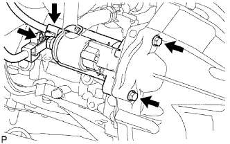
Install the starter with the 2 bolts.
- Torque:
- 37 N*m { 377 kgf*cm, 27 ft.*lbf }
-
Install the starter wire to terminal 30 with the nut.
- Torque:
- 9.8 N*m { 100 kgf*cm, 87 in.*lbf }
-
Connect the terminal cap.
-
Connect the starter connector.
-
-
INSTALL PROPELLER SHAFT WITH CENTER BEARING ASSEMBLY
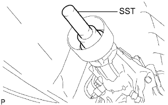
-
Снимите SST с удлинителя картера трансмиссии.
-
Установите карданный вал в удлинитель картера трансмиссии.
-
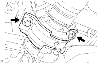
Закрепите кронштейн центрального опорного подшипника с помощью 2 пластин и 2 болтов. Затяните болты вручную до упора.
-
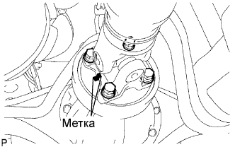
Совместите метки на фланце карданного вала и фланце дифференциала.
-
Установите карданный вал и закрепите его 4 болтами, 4 шайбами и 4 гайками.
- Torque:
- 88 Н*м { 897 кгс*см, 65 фунт-сила-футов }
-
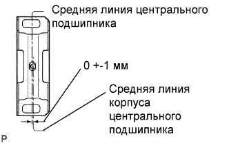
Разгрузите автомобиль. Осевые линии центрального подшипника и корпуса центрального подшипника (см. рисунок) должны отстоять друг от друга не более чем на 0 +- 1 мм (0 +- 0,04 дюйма). Измерьте расхождение вдоль передней/задней оси автомобиля.
-
Затяните 2 болта кронштейна центрального опорного подшипника.
- Torque:
- 36 Н*м { 367 кгс*см, 27 фунт-сила-футов }
-
-
INSTALL FRONT EXHAUST PIPE
-
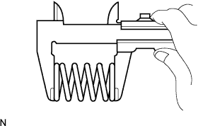
Using a vernier caliper, measure the free length of the compression spring.
Minimum length 40 mm (1.57 in.) If the length is less than the minimum, replace the compression spring.
-
Install the front pipe to the pipe support.
-
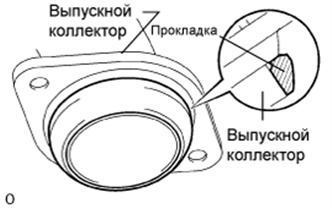
Install a new gasket to the exhaust manifold.
Tech Tips
Using a plastic-faced hammer, uniformly strike the gasket so that the gasket and exhaust manifold are properly fit.
Note
-
Be careful with the installation direction of the gasket.
-
Do not reuse the gasket.
-
To ensure a proper seal, do not use the front pipe to force the gasket onto the exhaust manifold.
-
-
Install the front pipe with the 2 compression springs and 2 bolts. Alternately tighten the bolts in several passes.
- Torque:
- 43 N*m { 438 kgf*cm, 32 ft.*lbf }
-
-
INSTALL HOOD ASSEMBLY
-
Install the hood with the 4 bolts.
- Torque:
- 13 N*m { 133 kgf*cm, 10 ft.*lbf }
-
Connect the washer nozzle hose.
-
Adjust the hood Click here.
-
-
INSTALL COOLER COMPRESSOR (w/ Air Conditioning System)
-
Loosely install the bolt labeled A to install the compressor.
-
Install the compressor completely by tightening the 4 bolts in the order shown in the illustration.
- Torque:
- 25 N*m { 250 kgf*cm, 18 ft.*lbf }
Note
In order to prevent misalignment, which causes belt rattle, tightening of the bolts must be performed in the order shown.
-
Connect the suction hose with the 2 bolts.
- Torque:
- 5.0 N*m { 51 kgf*cm, 44 in.*lbf }
-
Connect the compressor connector.
-
-
INSTALL OIL DIPSTICK GUIDE
-
Install a new O-ring and the guide with the bolt.
- Torque:
- 8.0 N*m { 82 kgf*cm, 71 in.*lbf }
-
-
INSTALL OIL DIPSTICK
-
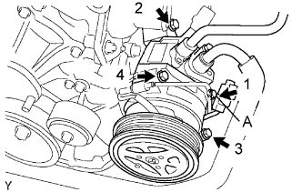
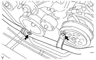
INSTALL VANE PUMP
-
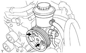
Install the vane pump with the 2 bolts.
- Torque:
- 21 N*m { 214 kgf*cm, 15 ft.*lbf }
-
Connect the PS oil pressure switch connector.
-
-
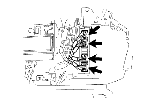
CONNECT ENGINE WIRE
-
Connect the 2 engine room junction block connectors and connect the wire clamp.
-
Connect the cable to the engine room junction block with the nut.
- Torque:
- 13 N*m { 133 kgf*cm, 10 ft.*lbf }
-
Install the engine room relay block cover (side).
-
Install the engine room relay block cover (upper).
-
Connect the ground wire with the bolt and clamp.
- Torque:
- 31 N*m { 316 kgf*cm, 23 ft.*lbf }
-
Connect the ground wire to the frame with the bolt so that it is within the range shown in the illustration.
- Torque:
- 13 N*m { 133 kgf*cm, 10 ft.*lbf }
-
Push the engine wire through the dash panel into the cabin. The wire should be within the range shown in the illustration.
-
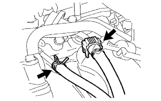
Connect the heated oxygen sensor connector and clamp with the bolt.
- Torque:
- 13 N*m { 133 kgf*cm, 10 ft.*lbf }
-
Connect the ECM connectors.
-
Connect the 4 ECM connectors.
-
Install the glove compartment door.
-
-
Connect the wire clamp to the engine mounting bracket front LH with the bolt.
-
-
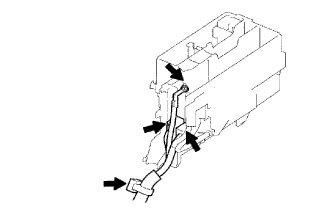
CONNECT FUEL HOSE
-
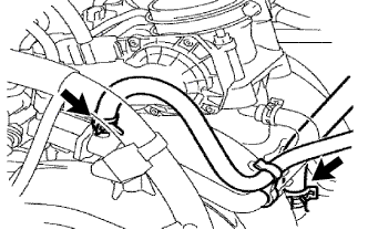
Connect the No. 2 fuel hose to the pressure regulator.
-
Connect the No. 1 fuel hose to the pulsation damper.
-
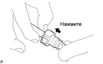
Check that there is no damage or contamination in the connected part of the pipe.
-
Align the axis of the connector with the axis of the pipe. Push the pipe into the connector until the connector makes a "click" sound. If the connection is tight, apply a small amount of fresh engine oil on the tip of the pipe.
-
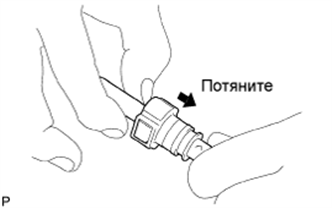
After having finished the connection, try to pull apart the pipe and the connector and confirm that they are securely connected.
-
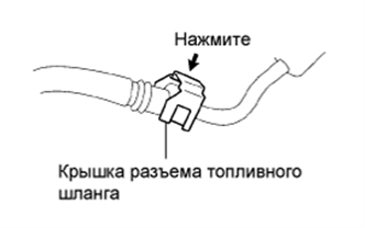
Attach the lock claws to the connector by pushing down on the cover, as shown in the illustration.
-
-
-
CONNECT HOSE
-
Connect the vacuum hose (for brake master cylinder).
-
Connect the hose to the VSV for EVAP.
-
-
INSTALL RADIATOR ASSEMBLY
-
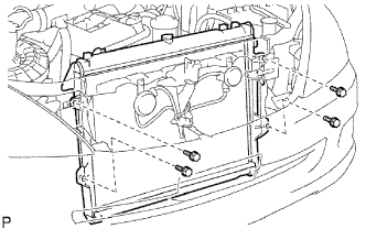
Install the radiator with the 4 bolts.
- Torque:
- 12 N*m { 122 kgf*cm, 9 ft.*lbf }
-

Attach the 4 clamps to the radiator side as shown in the illustration.
-
Connect the 2 airbag sensor front connectors.
-
-
INSTALL FAN PULLEY
-
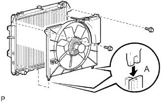
INSTALL FAN SHROUD
-
Install the fan pulley to the water pump.
-
Place the shroud together with the fluid coupling fan between the radiator and engine.
Note
Be careful not to damage the radiator core.
-
Install the coupling fan to the water pump with the 4 nuts. Tighten the nuts as much as possible by hand.
-
Attach the shroud's claws to the radiator as shown in A in the illustration.
-
Install the shroud with the 2 bolts.
- Torque:
- 5.0 N*m { 51 kgf*cm, 44 in.*lbf }
-
Connect the reservoir hose to the radiator tank upper.
-
Install the drive belt Click here.
-
Tighten the 4 nuts of the fluid coupling fan.
- Torque:
- 25 N*m { 255 kgf*cm, 18 ft.*lbf }
-
-
INSTALL DRIVE BELT
-
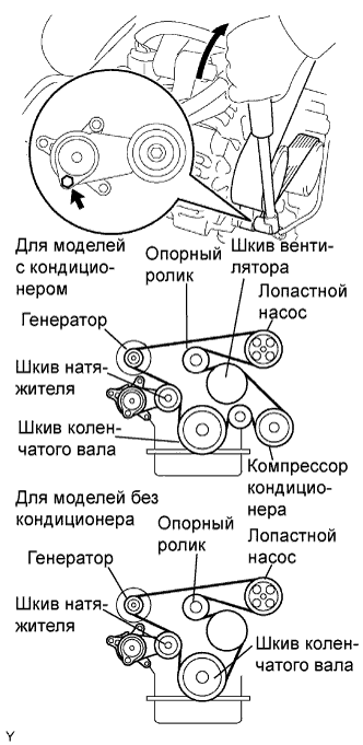
Install the drive belt to the pulleys except the drive belt tensioner pulley.
-
Use the hexagon-shaped part indicated by the arrow in the illustration to move the tensioner pulley downward and then install the drive belt to the tensioner pulley.
Note
-
The backside of the drive belt should face the tensioner pulley.
-
Check that the drive belt is properly set to each pulley.
-
-
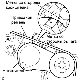
After a new belt has been installed, check that the tensioner indicator mark is within range A shown in the illustration.
-
-
CONNECT RADIATOR OUTLET HOSE
-
CONNECT RADIATOR INLET HOSE
-
INSTALL RADIATOR GRILLE
-
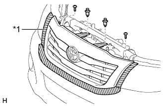
Обозначения на рисунке *1 Защитная клейкая лента Наклейте защитную клейкую ленту вокруг решетки радиатора.
-
Выверните 2 винта и освободите 2 фиксатора.
-
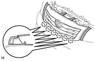
Расцепите 6 захватов и снимите решетку радиатора.
-
-
INSTALL INTAKE AIR CONNECTOR AND AIR CLEANER ASSEMBLY
-
Install the air cleaner and intake air connector assembly with the 4 bolts, and tighten the hose clamp.
- Torque:
- 14 N*m { 143 kgf*cm, 10 ft.*lbf, for air cleaner }
- 8.0 N*m { 82 kgf*cm, 71 in.*lbf, for intake air connector }
- 5.0 N*m { 51 kgf*cm, 44 in.*lbf, for hose clamp }
-
Connect the MAF meter connector and wire harness clamps.
-
Connect the No. 2 ventilation hose.
-
Connect the vacuum hose.
-
-
CONNECT CABLE TO NEGATIVE BATTERY TERMINAL
-
ADD ENGINE OIL
-
Clean and install the oil drain plug with a new gasket.
- Torque:
- 37.5 N*m { 382 kgf*cm, 28 ft.*lbf }
-
Add fresh engine oil.
Standard capacity Item Capacity Drain and refill with oil filter change 5.6 liters (5.9 US qts, 4.9 Imp. qts) Drain and refill without oil filter change 5.3 liters (5.6 US qts, 4.7 Imp. qts) Dry fill 6.3 liters (6.7 US qts, 5.5 Imp. qts) -
Install the oil filler cap.
-
-
ADD ENGINE COOLANT
-
Tighten all the plugs and fill the radiator with TOYOTA Super Long Life Coolant (SLLC).
- Torque:
- 24.5 N*m { 250 kgf*cm, 18 ft.*lbf, for cylinder block drain cock plug }
Standard capacity 7.0 liters (7.4 US qts, 6.2 Imp. qts) -
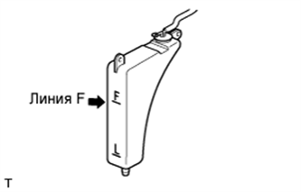
Fill the radiator reservoir with TOYOTA Super Long Life Coolant (SLLC) to the F line.
Tech Tips
-
TOYOTA vehicles are filled with TOYOTA SLLC at the factory. In order to avoid damage to the engine cooling system and other technical problems, only use TOYOTA SLLC or similar high quality ethylene glycol based non-silicate, non-amine, non-nitrite, non-borate coolant with long-life hybrid organic acid technology (coolant with long-life hybrid organic acid technology consists of a combination of low phosphates and organic acids).
-
Please contact your TOYOTA dealer for further details.
Note
Never use water as a substitute for engine coolant.
-
-
Press the inlet and outlet radiator hoses several times by hand, and then check the level of the coolant.
If the coolant level drops below the F line, add TOYOTA SLLC to the F line.
-
Install the radiator cap.
-
Bleed air from the cooling system.
-
Warm up the engine until the thermostat opens. While the thermostat is open, circulate the coolant for several minutes.
-
Maintain the engine speed at 2,500 to 3,000 rpm.
-
Press the inlet and outlet radiator hoses several times by hand to bleed air.
CAUTION:
When pressing the radiator hoses:
-
Wear protective gloves.
-
Be careful as the radiator hoses are hot.
-
Keep your hands away from the radiator fan.
-
-
-
Stop the engine and wait until the coolant cools down to ambient temperature.
CAUTION:
Do not remove the radiator cap while the engine and radiator are still hot. Pressurized, hot engine coolant and steam may be released and cause serious burns.
-
Check the coolant level in the radiator reservoir.
If the coolant level is below the L line, add SLLC to the reservoir F line.
-
-
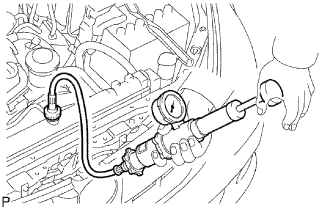
CHECK FOR FUEL LEAKS
-
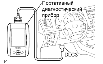
Connect the intelligent tester to the DLC3.
-
Turn the ignition switch ON.
Note
Do not start the engine.
-
Push the intelligent tester main switch ON.
-
Select the Active Test and enter the following menus: Powertrain / Engine and ECT / Active Test / Control the Fuel Pump / Speed.
-
-
Check for fuel leaks.
-
Check that there are no fuel leaks after performing maintenance anywhere on the fuel system.
-
-
-
CHECK FOR OIL LEAKS
-
Start the engine, and check that there are no oil leaks after performing maintenance.
-
-
CHECK FOR COOLANT LEAKS
CAUTION:
Do not remove the radiator cap while the engine and radiator are still hot. Pressurized, hot engine coolant and steam may be released and cause serious burns.
-
Fill the radiator with coolant and attach a radiator cap tester.
-
Warm up the engine.
-
Using a radiator cap tester, increase the pressure inside the radiator to 118 kPa (1.2 kgf/cm2, 17.1 psi), and check that the pressure does not drop.
If the pressure drops, check the hoses, radiator and water pump for leaks. If no external leaks are found, check the cylinder block and head.
-
-
PERFORM INITIALIZATION
-
Perform initialization Click here.
Note
Certain systems need to be initialized after disconnecting the cable from the negative (-) battery terminal.
-
-
INSTALL NO. 1 ENGINE UNDER COVER
-
Install the No. 1 under cover with the 4 bolts.
- Torque:
- 28 N*m { 286 kgf*cm, 21 ft.*lbf }
-
-
CHECK ENGINE IDLE SPEED AND IGNITION TIMING
-
Warm up and stop the engine.
Note
A warmed up engine should have an engine coolant temperature of over 80°C (176°F), have an engine oil temperature of 60°C (140°F), and the engine rpm should be stabilized.
-
Check the idle speed control system.
-
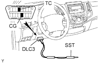
Using SST, connect terminals TC and CG of the DLC3.
- SST
- 09843-18040
-
Start the engine at idle.
Note
-
Confirm the terminal numbers before connecting them. Connection with a wrong terminal can damage the engine.
-
Turn off all electrical systems before connecting the terminals.
-
When checking ISC function, the transmission should be in the neutral position.
-
-
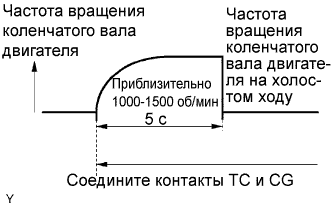
After connecting terminals (TC and CG), check that the engine speed changes to approximately 1,000 to 1,500 rpm for 5 seconds, and then returns to idle speed.
If the result is not as specified, check the throttle body, DTC Click here and wire harness.
-
-
-
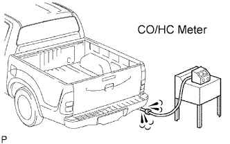
CHECK CO/HC
-
Start and warm up the engine.
-
Run the engine at 2,500 rpm for approximately 180 seconds and idle the engine.
-
Insert CO/HC meter testing probe at least 40 cm (1.3 ft.) into the tailpipe.
-
Check CO/HC concentration at idle.
Standard idle CO concentration 0 to 0.5 % Standard idle HC concentration Applicable local regulation -
If the CO/HC concentration is not as specified, perform troubleshooting in the order given below.
-
Check the heated oxygen sensor operation Click here.
-
See the table below for possible causes, and then inspect and repair the applicable causes if necessary.
CO HC Problems Causes Normal High Rough idle
-
Faulty ignitions:
-
Incorrect timing
-
Plugs are contaminated, shorted or gaps are defective
-
Incorrect valve clearance
-
Leaks in intake and exhaust valves
-
Leaks in cylinders
Low High Rough idle
(Fluctuating HC reading)
-
Vacuum leaks:
-
PCV hoses
-
Intake manifold
-
Throttle body
-
Brake booster line
-
Lean mixture causing misfire
High High Rough idle
(Black smoke from exhaust)
-
Restricted air filter
-
Plugged PCV valve
-
Faulty SFI system:
-
Faulty pressure regulator
-
Defective ECT sensor
-
Defective Mass Air Flow (MAF) meter
-
Faulty ECM
-
Faulty injectors
-
Faulty throttle position sensor
-
-
-
-
CHECK FUNCTION OF THROTTLE BODY
-
Проверьте, слышен ли звук работающего электродвигателя привода дроссельной заслонки.
-
Включите зажигание.
-
Нажимая педаль акселератора, убедитесь в наличии звука работающего двигателя. Убедитесь, что двигатель не создает шум трения.
Если слышен шум трения, замените корпус дроссельной заслонки.
-
-
Проверьте датчик положения дроссельной заслонки.
-
Подсоедините портативный диагностический прибор к DLC3.
-
Включите зажигание.
-
Убедитесь, что в режиме Current Data процентное значение угла поворота дроссельной заслонки (Throttle Pos) не выходит за пределы номинального диапазона.
Номинальное значение открывания дроссельной заслонки 60% или более Note
Во время проверки степени открывания дроссельной заслонки рычаг переключения передач должен находиться в нейтральном положении.
Если значение составляет менее 60%, замените корпус дроссельной заслонки.
-
-