STEERING GEAR INSTALLATION

PROCEDURE
-
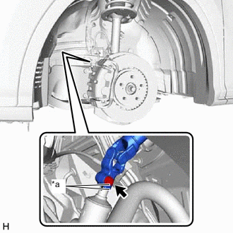
INSTALL TIE ROD ASSEMBLY LH
-
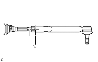
*a Matchmark Install the lock nut and tie rod assembly LH to the steering gear assembly until the matchmarks are aligned.
Tech Tips
After adjusting the toe-in, tighten the lock nut.
-
-
INSTALL TIE ROD ASSEMBLY RH
Tech Tips
Perform the same procedure as for the LH side.
-
INSTALL STEERING LINK ASSEMBLY
-
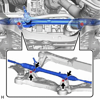
Install the steering link assembly to the front frame assembly with the 2 bolts and 2 nuts.
- Torque:
- 70 N*m { 714 kgf*cm, 52 ft.*lbf }
Note
-
Because the nut has its own stopper, do not turn the nut. Tighten the bolt with the nut secured.
-
Make sure to tighten the bolts starting from the steering link assembly pinion shaft side.
-
-
INSTALL FRONT STABILIZER BAR
-
Install the front stabilizer bar to the front frame assembly.
-
-
INSTALL FRONT NO. 2 STABILIZER BRACKET LH
-
Install the front No. 2 stabilizer bracket LH to the front frame assembly.
-
-
INSTALL FRONT NO. 2 STABILIZER BRACKET RH
Tech Tips
Perform the same procedure as for the LH side.
-
INSTALL FRONT NO. 1 STABILIZER BRACKET LH
-
Install the front No. 1 stabilizer bracket LH to the front frame assembly with the 2 bolts.
- Torque:
- 93 N*m { 948 kgf*cm, 69 ft.*lbf }
-
-
INSTALL FRONT NO. 1 STABILIZER BRACKET RH
Tech Tips
Perform the same procedure as for the LH side.
-
CONNECT TIE ROD ASSEMBLY LH
-
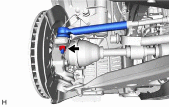
Connect the tie rod assembly LH to the steering knuckle LH with the nut.
- Torque:
- 49 N*m { 500 kgf*cm, 36 ft.*lbf }
Note
-
Do not damage the ball joint dust cover.
-
Further tighten the nut up to 60° if the holes for the cotter pin are not aligned.
-
Install a new cotter pin.
-
-
CONNECT TIE ROD ASSEMBLY RH
Tech Tips
Perform the same procedure as for the LH side.
-
CONNECT FRONT STABILIZER LINK ASSEMBLY LH
-
Install the front stabilizer link assembly LH to the front stabilizer bar with the nut.
- Torque:
- 76 N*m { 775 kgf*cm, 56 ft.*lbf }
Tech Tips
If the ball joint turns together with the nut, use a 6 mm hexagon wrench to hold the stud bolt.
-
-
CONNECT FRONT STABILIZER LINK ASSEMBLY RH
Tech Tips
Perform the same procedure as for the LH side.
-
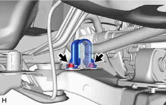
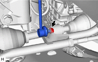
CONNECT STEERING INTERMEDIATE SHAFT ASSEMBLY
-
*a Matchmark Align the matchmarks on the steering intermediate shaft assembly and steering link assembly.
-
Connect the steering intermediate shaft assembly to the steering link assembly.
-
Install a new bolt.
- Torque:
- 64 N*m { 653 kgf*cm, 47 ft.*lbf }
-
-
INSTALL NO. 2 ENGINE UNDER COVER
for 8AR-FTS:
for 2GR-FKS:
-
INSTALL FRONT WHEELS
-
INSPECT AND ADJUST FRONT WHEEL ALIGNMENT