CRUISE CONTROL SYSTEM(except 1ND-TV, 8NR-FTS) Clutch Switch Circuit
| DTC Code | DTC Name |
|---|---|
| Clutch Switch Circuit |
DESCRIPTION
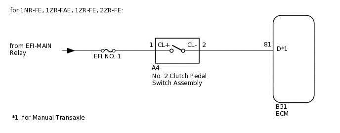
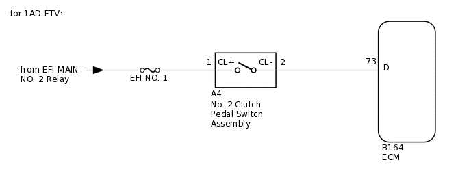
While depressing the clutch pedal, the No. 2 clutch pedal switch sends a signal to terminal (D) of the ECM. The ECM cancels cruise control when terminal (D) receives the signal.
WIRING DIAGRAM
CAUTION / NOTICE / HINT
Inspect the fuses for circuits related to this system before performing the following procedure.
PROCEDURE
INSPECT NO. 2 CLUTCH PEDAL SWITCH ASSEMBLY
Inspect the No. 2 clutch pedal switch assembly.
Result
Proceed to
OK
NG
CHECK HARNESS AND CONNECTOR (NO. 2 CLUTCH PEDAL SWITCH ASSEMBLY - BATTERY)
Disconnect the No. 2 clutch pedal switch assembly connector.
Measure the voltage according to the value(s) in the table below.
Standard Voltage
Tester Connection
Condition
Specified Condition
A4-1 - Body ground
Ignition switch ON
11 to 14 V
A4-1 - Body ground
Ignition switch off
Below 1 V
Reconnect the No. 2 clutch pedal switch assembly connector.
Result
Proceed to
OK
NG
NG REPAIR OR REPLACE HARNESS OR CONNECTOR (NO. 2 CLUTCH PEDAL SWITCH ASSEMBLY - BATTERY)
CHECK HARNESS AND CONNECTOR (ECM - NO. 2 CLUTCH PEDAL SWITCH ASSEMBLY)
Disconnect the No. 2 clutch pedal switch assembly connector.
Disconnect the ECM connector.
Measure the resistance according to the value(s) in the table below.
Standard Resistance (Check for Open)
Table 1. for 1NR-FE, 1ZR-FAE, 1ZR-FE, 2ZR-FE Tester Connection
Condition
Specified Condition
B31-81 (D) - A4-2 (CL-)
Always
Below 1 Ω
Table 2. for 1AD-FTV Tester Connection
Condition
Specified Condition
B164-73 (D) - A4-2 (CL-)
Always
Below 1 Ω
Standard Resistance (Check for Short)
Table 3. for 1NR-FE, 1ZR-FAE, 1ZR-FE, 2ZR-FE Tester Connection
Condition
Specified Condition
B31-81 (D) or A4-2 (CL-) - Body ground
Always
10 kΩ or higher
Table 4. for 1AD-FTV Tester Connection
Condition
Specified Condition
B164-73 (D) or A4-2 (CL-) - Body ground
Always
10 kΩ or higher
Reconnect the No. 2 clutch pedal switch assembly connector.
Reconnect the ECM connector.
Result
Proceed to
OK
NG
NG REPAIR OR REPLACE HARNESS OR CONNECTOR (NO. 2 CLUTCH PEDAL SWITCH ASSEMBLY - ECM)