OUTER REAR VIEW MIRROR INSTALLATION
Tech Tips
-
Use the same procedure for RHD and LHD vehicles.
-
The procedure listed below is for LHD vehicles.
-
Use the same procedure for the RH and LH sides.
-
The procedure listed below is for the LH side.
-
A bolt without a torque specification is shown in the standard bolt chart Click here.
-
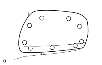
INSTALL OUTER MIRROR COVER LH (w/o Side Turn Signal Light)
-
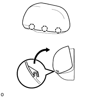
Attach the 3 claws as shown in the illustration.
-
Attach the 6 claws to install the mirror cover LH.
-
After installing the outer mirror cover, check that there is no gap between the cover and mirror body.
Tech Tips
If there is a gap between the cover and body, noise will occur during driving.
-
-
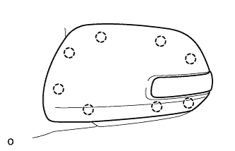
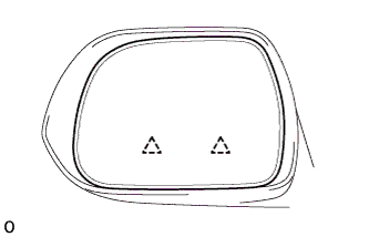
INSTALL OUTER MIRROR COVER LH (w/ Side Turn Signal Light)
-
Attach the 2 claws as shown in the illustration.
-
Attach the 6 claws to install the outer mirror cover LH.
-
After installing the outer mirror cover, check that there is no gap between the cover and mirror body.
If there is a gap between the cover and body, noise will occur during driving.
-
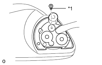
Text in Illustration *1 Adhesive Using a T25 "TORX" socket wrench, install the screw.
Tech Tips
-
Clean the threads of the screw with non-residue solvent.
-
Apply adhesive to the threads of the screw.
Adhesive Toyota Genuine Adhesive 1324, Three Bond 1324 or equivalent
-
-
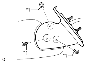
Text in Illustration *1 Adhesive Using a T25 "TORX" socket wrench, install the screws.
Tech Tips
-
Clean the threads of the screws with non-residue solvent.
-
Apply adhesive to the threads of the screws.
Adhesive Toyota Genuine Adhesive 1324, Three Bond 1324 or equivalent
-
-
Attach the 5 claws.
-
Install the rubber base with the screw.
-
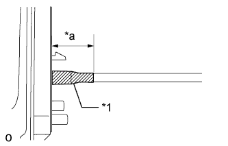
Text in Illustration *1 Tape *a 40 mm (1.58 in.) Apply new tape as shown in the illustration.
-
-
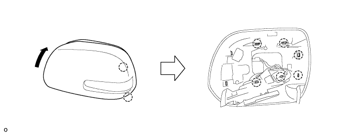
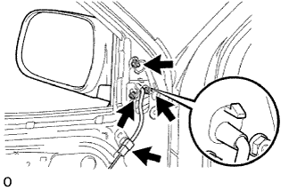
INSTALL OUTER MIRROR LH
-
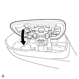
Attach the 2 claws as shown in the illustration.
-
Attach the 2 clips to install the outer mirror LH.
Note
Do not push in the glass with excessive force. Doing so may break the mirror surface.
-
-
INSTALL OUTER REAR VIEW MIRROR ASSEMBLY LH
-
Install the outer rear view mirror assembly LH with the 3 nuts.
- Torque:
- 8.0 N*m { 82 kgf*cm, 71 ft.*lbf }
-
w/ Power Mirror Control System:
Connect the connector.
-
-
INSTALL FRONT DOOR TRIM BOARD SUB-ASSEMBLY LH
-
for Double Cab:
-
Attach the 8 clips to install the front door trim board.
-
Install the screw and clip.
-
-
for Single Cab, for Extra Cab:
-
Attach the 9 clips to install the front door trim board.
-
Install the screw and clip.
-
-
-
INSTALL DOOR PULL HANDLE
-
Install the door pull handle with the screw.
-
-
INSTALL FRONT DOOR LOWER FRAME BRACKET GARNISH LH
-
Attach the 2 clips to install the front door lower frame bracket garnish.
-
-
INSTALL POWER WINDOW REGULATOR SWITCH ASSEMBLY WITH FRONT DOOR ARMREST BASE PANEL RH (w/ Power Window)
-
Connect the connector.
-
Attach the 4 claws and 2 clips to install the power window regulator master switch assembly with front door armrest base panel.
-
-
INSTALL POWER WINDOW REGULATOR MASTER SWITCH ASSEMBLY WITH FRONT DOOR ARMREST BASE PANEL LH (w/ Power Window)
-
Connect the connector.
-
Attach the 4 claws and 2 clips to install the power window regulator switch assembly with front door armrest base panel.
-
-
INSTALL FRONT DOOR WINDOW REGULATOR HANDLE ASSEMBLY (w/o Power Window)
-
Temporarily install the front door window regulator handle, fully close the window, and then remove the front door window regulator handle.
-
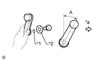
Text in Illustration *1 Snap Ring *2 Plate *a Front Side Install the plate and snap ring to the front door window regulator handle.
-
Install the front door window regulator handle to the front door window regulator as shown in the illustration.
Standard Area Specified Condition A 18 to 42°
-