THEFT DETERRENT SYSTEM TERMINALS OF ECU
-
CHECK INSTRUMENT PANEL JUNCTION BLOCK ASSEMBLY AND MAIN BODY ECU (MULTIPLEX NETWORK BODY ECU)
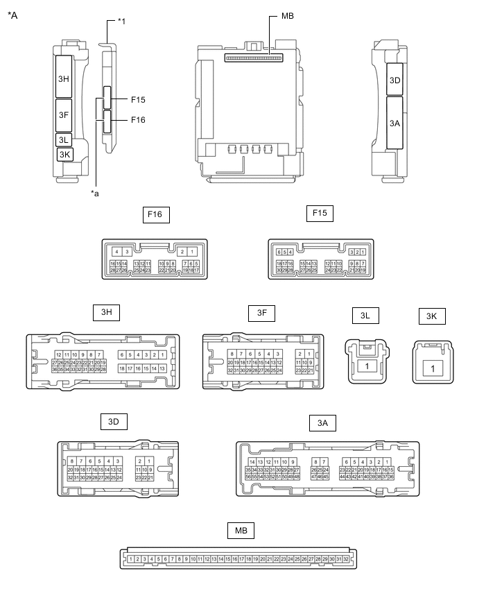
*A Main Body ECU (Multiplex Network Body ECU) with 2 Connectors - - *1 Main Body ECU (Multiplex Network Body ECU) - - *a 2 Connectors - - 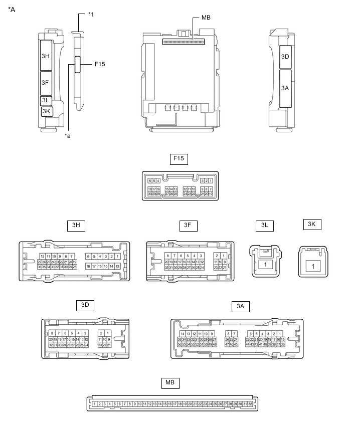
*A Main Body ECU (Multiplex Network Body ECU) with 1 Connector - - *1 Main Body ECU (Multiplex Network Body ECU) - - *a 1 Connector - -
-
Remove the main body ECU (multiplex network body ECU) from the instrument panel junction block assembly.
-
for LHD: Click here
-
for RHD: Click here
-
-
Reconnect the instrument panel junction block assembly connectors.
-
Measure the resistance and voltage according to the value(s) in the table below.
Tech Tips
Measure the values on the wire harness side with the connector disconnected.
Terminal No. (Symbol) Wiring Color Terminal Description Condition Specified Condition MB-31 (BECU) - Body ground - Battery power supply Always 11 to 14 V MB-32 (IG) - Body ground - Ignition power supply (IG signal) Ignition switch off Below 1 V Ignition switch ON 11 to 14 V MB-30 (ACC) - Body ground - Ignition power supply (ACC signal) Ignition switch off Below 1 V Ignition switch ACC 11 to 14 V MB-11 (GND1) - Body ground - Ground Always Below 1 Ω F15-6 (FLCY) - Body ground R - Body ground Front door courtesy light switch assembly (for LH) input Front door LH closed 10 kΩ or higher Front door LH open Below 1 Ω F15-27 (FRCY) - Body ground BR - Body ground Front door courtesy light switch assembly (for RH) input Front door RH closed 10 kΩ or higher Front door RH open Below 1 Ω MB-13 (LCTY) - Body ground - Rear door courtesy light switch assembly (for LH) input Rear door LH closed 10 kΩ or higher Rear door LH open Below 1 Ω MB-2 (RCTY) - Body ground - Rear door courtesy light switch assembly (for RH) input Rear door RH closed 10 kΩ or higher Rear door RH open Below 1 Ω MB-4 (BCTY) - Body ground - Back door courtesy light switch input Back door closed 10 kΩ or higher Back door open Below 1 Ω F15-11 (HCTY) - Body ground GR - Body ground Engine hood courtesy switch input Engine hood open 10 kΩ or higher Engine hood closed Below 1 Ω MB-3 (KSW) - Body ground*1 - Unlock warning switch signal No key in ignition key cylinder 10 kΩ or higher Key in ignition key cylinder Below 1 Ω
-
*1: w/o Entry and Start System
-
-
Install the main body ECU (multiplex network body ECU) to instrument panel junction block assembly.
-
for LHD: Click here
-
for RHD: Click here
-
-
Measure the voltage and check for pulses according to the value(s) in the table below.
Terminal No. (Symbol) Wiring Color Terminal Description Condition Specified Condition 3D-13 (LSFL) - Body ground B - Body ground Front door LH unlock detection switch input Front door LH unlocked Below 1 V Front door LH locked Pulse generation 3D-12 (LSFR) - Body ground GR - Body ground Front door RH unlock detection switch input Front door RH unlocked Below 1 V Front door RH locked Pulse generation F15-29 (L2) - Body ground G - Body ground Driver door key-linked lock input Driver door key cylinder turned to lock position Below 1 V Driver door key cylinder off Pulse generation F15-2 (UL3) - Body ground L - Body ground Driver door key-linked unlock input Driver door key cylinder turned to unlock position Below 1 V Driver door key cylinder off Pulse generation 3D-14 (LSR) - Body ground LG - Body ground Rear door LH and Rear door RH unlock detection switch input Rear door LH or Rear door RH unlocked Below 1 V Rear door LH and Rear door RH locked Pulse generation F16-12 (ISIF) - Body ground*1 G - Body ground Intrusion sensor (theft warning ultrasonic sensor) signal input No moving object detected by sensor 11 to 14 V Theft deterrent system changed from disarmed state to arming preparation state Pulse generation
(See waveform 1)
F16-13 (SSW1) - Body ground*1 LG - Body ground Intrusion sensor cancel switch signal Intrusion sensor cancel switch not pushed Pulse generation Intrusion sensor cancel switch pushed Below 1 V F15-7 (GPBS) - Body ground*1 P - Body ground Glass breakage sensor signal input Glass breakage sensor circuit not open Below 1 V 3A-20 (SH) - Body ground*2 LG - Body ground Security horn assembly drive Security horn assembly sounding
(Theft deterrent system in alarm sounding state)
Pulse generation
(Below 1 V ← → 11 to 14 V)
F16-18 (SSCL) - Body ground*1 SB - Body ground Theft warning siren assembly drive Theft warning siren assembly sounding
(Theft deterrent system in alarm sounding state)
Pulse generation
(Below 1 V ← → 11 to 14 V)
3F-27 (HORN) - Body ground SB - Body ground Vehicle horns drive Vehicle horns sounding
(Theft deterrent system in alarm sounding state)
Pulse generation
(Below 1 V ← → 11 to 14 V)
-
*1: w/ Intrusion Sensor
-
*2: w/o Intrusion Sensor
-
-
Using an oscilloscope, check the waveform.
Tech Tips
The waveform shown in the illustration is an example for reference only. Noise, chattering, etc. are not shown.
-
Waveform 1 (Reference)
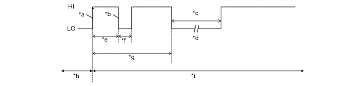
*a IOUT Initial Signal *b IOUT Initial Response *c Approximately 1.0 Second *d Initial Diagnosis *e Approximately 1.0 to 1.6 Seconds *f Approximately 0.05 Seconds *g Approximately 5.5 Seconds *h Disarmed State *i Arming Preparation State - -
-
-