AIR CONDITIONING UNIT(for VALEO Made) DISASSEMBLY
CAUTION / NOTICE / HINT
Tech Tips
-
Use the same procedure for RHD and LHD vehicles.
-
The procedure listed below is for LHD vehicles.
PROCEDURE
-
PRECAUTION
Note
Make sure to perform initialization after replacing the air conditioning radiator damper servo sub-assembly. If initialization is not performed, the air conditioner unit assembly will not perform properly as the air conditioning amplifier assembly will not be able to recognize the position of the air conditioning radiator damper sub-assembly.
-
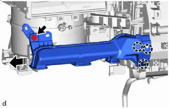
REMOVE NO. 2 AIR DUCT (for LHD)
-


Remove in this Direction Remove the screw.
-
Disengage the claws to remove the No. 2 air duct as shown in the illustration.
-
-
REMOVE NO. 1 AIR DUCT (for RHD)
-
Remove in this Direction Remove the screw.
-
Disengage the claws to remove the No. 1 air duct as shown in the illustration.
-
-
REMOVE AIR CONDITIONING DUCT SUB-ASSEMBLY
-
Disengage the guide to remove the air conditioning duct sub-assembly.
-
-
REMOVE COVER (w/o Rear Air Duct)
-
Disengage the claws to remove the cover.
-
-
REMOVE NO. 3 INSTRUMENT PANEL WIRE (w/ PTC Heater)
-
Disconnect the connector.
-
Disengage the clamps to remove the No. 3 instrument panel wire.
-
-
REMOVE NO. 3 COOLER UNIT DRAIN HOSE
-
Remove the No. 3 cooler unit drain hose.
-
-
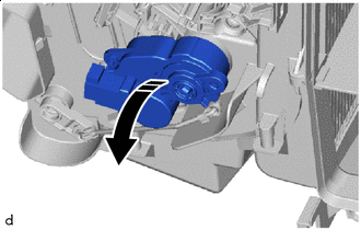
REMOVE BLOWER ASSEMBLY
-
REMOVE HEATER COVER (w/o PTC Heater)
-
Remove in this Direction Remove the 2 screws and heater cover as shown in the illustration.
-
-
REMOVE NO. 2 HEATER COVER (w/ PTC Heater)
-
Remove the screw and No. 2 heater cover.
-
-
REMOVE QUICK HEATER ASSEMBLY (w/ PTC Heater)
-
Remove in this Direction Remove the 2 screws and quick heater assembly as shown in the illustration.
-
-
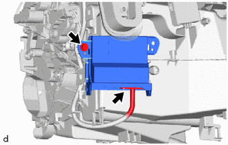
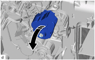
REMOVE AIR CONDITIONING AMPLIFIER ASSEMBLY
-
for LHD:
-
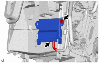
Disconnect the connector.
-
Remove the screw.
-
Remove in this Direction (1) 
Remove in this Direction (2) Disengage the guides to remove the air conditioning amplifier assembly as shown in the illustration.
-
-
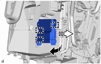
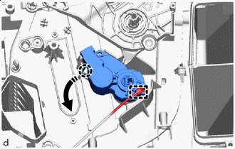
for RHD:
-
Disconnect the connector.
-
Remove the screw.
-
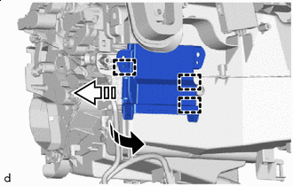
Remove in this Direction (1) Remove in this Direction (2) Disengage the guides to remove the air conditioning amplifier assembly as shown in the illustration.
-
-
-
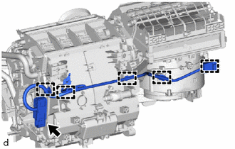
REMOVE AIR CONDITIONING HARNESS ASSEMBLY
-
for Automatic Air Conditioning System:
-
Disconnect the 5 connectors.
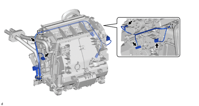
-
Disengage clamps to remove the air conditioning harness assembly.
-
-
for Manual Air Conditioning System:
-
Disconnect 3 connectors.
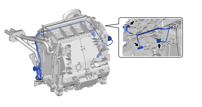
-
Disengage clamps to remove the air conditioning harness assembly.
-
-
-
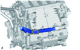
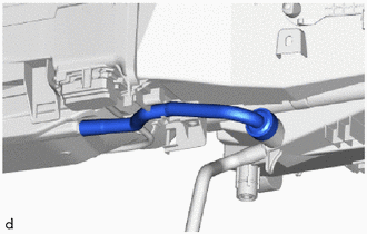
REMOVE DRAIN COOLER HOSE
-
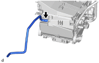
Remove the drain cooler hose.
-
-
REMOVE NO. 2 COOLER UNIT DRAIN HOSE
-
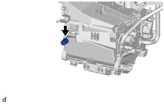
Remove the No. 2 cooler unit drain hose.
-
-
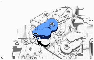
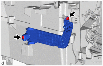
REMOVE NO. 1 AIR CONDITIONING RADIATOR DAMPER SERVO SUB-ASSEMBLY (for Automatic Air Conditioning System)
-
for Upper LH Side:
-
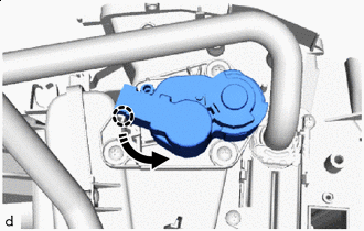
Remove in this Direction Turn the No. 1 air conditioning radiator damper servo sub-assembly to disengage the claw as shown in the illustration.
-
Remove in this Direction Remove the No. 1 air conditioning radiator damper servo sub-assembly as shown in the illustration.
-
-
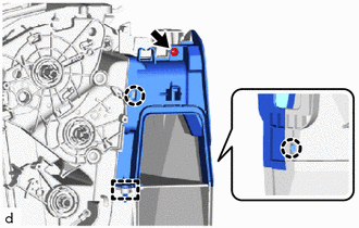
for Lower LH Side:
-
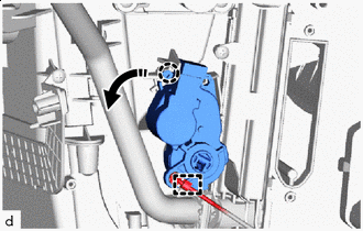
Remove in this Direction Disengage the snap.
-
Turn the No. 1 air conditioning radiator damper servo sub-assembly to disengage the claw as shown in the illustration.
-
Remove in this Direction Remove the No. 1 air conditioning radiator damper servo sub-assembly as shown in the illustration.
-
-
for Upper RH Side:
-

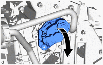
Remove in this Direction Turn the No. 1 air conditioning radiator damper servo sub-assembly to disengage the claw.
-
Remove in this Direction Remove the No. 1 air conditioning radiator damper servo sub-assembly as shown in the illustration.
-
-
for Lower RH Side:
-
Remove in this Direction Disengage the snap.
-
Turn the No. 1 air conditioning radiator damper servo sub-assembly to disengage the claw as shown in the illustration.
-
Remove in this Direction Remove the No. 1 air conditioning radiator damper servo sub-assembly as shown in the illustration.
-
-
-
REMOVE NO. 1 AIR CONDITIONING RADIATOR DAMPER SERVO SUB-ASSEMBLY (for Manual Air Conditioning System)
-
for Upper RH Side:
-
Remove in this Direction Turn the No. 1 air conditioning radiator damper servo sub-assembly to disengage the claw as shown in the illustration.
-

Remove in this Direction Remove the No. 1 air conditioning radiator damper servo sub-assembly as shown in the illustration.
-
-
for Lower RH Side:
-
Remove in this Direction Disengage the snap.
-
Turn the No. 1 air conditioning radiator damper servo sub-assembly to disengage the claw as shown in the illustration.
-

Remove in this Direction Remove the No. 1 air conditioning radiator damper servo sub-assembly as shown in the illustration.
-
-
-
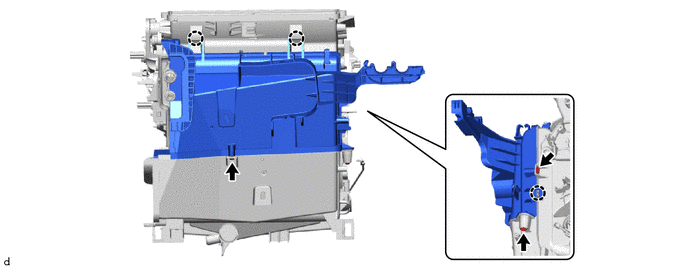
REMOVE NO. 2 AIR CONDITIONING RADIATOR DAMPER SERVO SUB-ASSEMBLY
-
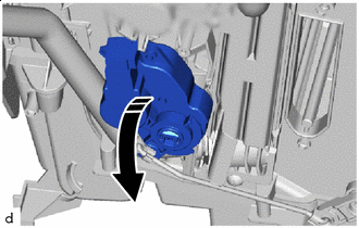
Remove in this Direction Turn the No. 2 air conditioning radiator damper servo sub-assembly to disengage the claw as shown in the illustration.
-
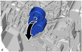
Remove in this Direction Remove the No. 2 air conditioning radiator damper servo sub-assembly as shown in the illustration.
-
-
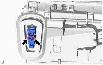
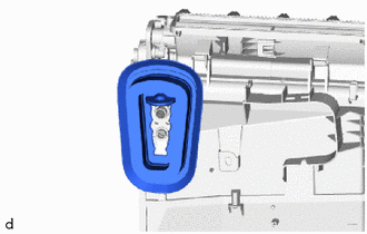
REMOVE HEATER PIPE GROMMET
-
Remove the heater pipe grommet.
-
-
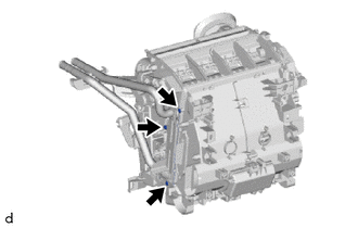
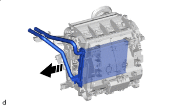
REMOVE HEATER CLAMP
-
Remove the screw.
-
Disengage the claws to remove the heater clamp.
-
-
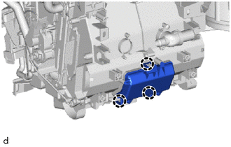
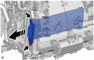
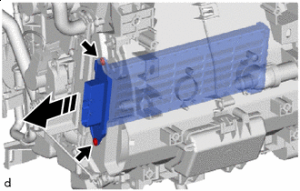
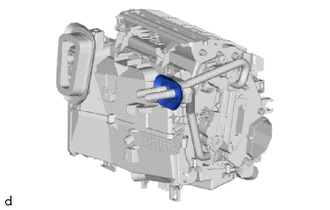
REMOVE HEATER RADIATOR UNIT SUB-ASSEMBLY
-
Remove the 3 screws.
-
Remove in this Direction Remove the heater radiator unit sub-assembly as shown in the illustration.
Note
Prepare a drain pan or cloth in case the coolant leaks.
-
-
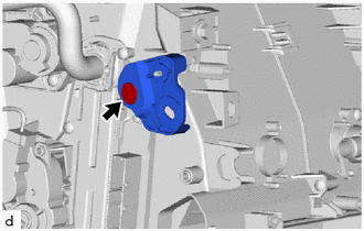
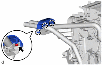
REMOVE COOLER EXPANSION VALVE
-
Using a 4 mm hexagon socket wrench, remove the 2 hexagon bolts and cooler expansion valve.
-
Remove the 2 O-rings from the No. 1 cooler evaporator sub-assembly.
-
Remove the grommet.
-
-
REMOVE HEAT EXCHANGER CASE
-
Remove the 2 screws and the bracket.
-
Disengage the claws and guide, and remove the screw to remove the heat exchanger case.
-
-
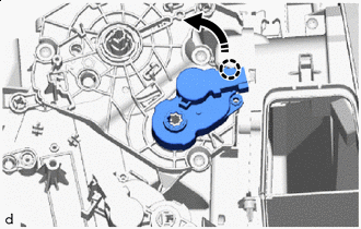
REMOVE RADIATOR CASE SUB-ASSEMBLY
-
Remove the 3 screws.
-
Disengage the claws to remove the radiator case sub-assembly.
-
-
REMOVE NO. 1 COOLER EVAPORATOR SUB-ASSEMBLY
-
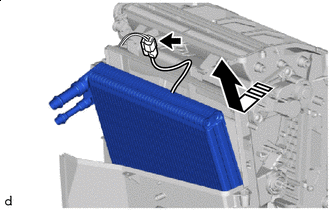
Remove in this Direction Disconnect the the connector.
-
Remove the No. 1 cooler evaporator sub-assembly with No. 1 cooler thermistor as shown in the illustration.
-
-
REMOVE NO. 2 RADIATOR CASE SUB-ASSEMBLY
-
Remove the 6 screws and the No. 2 radiator case sub-assembly.
-
-
REMOVE NO. 1 COOLER THERMISTOR