STEERING COLUMN ASSEMBLY REMOVAL
CAUTION / NOTICE / HINT
Some of these service operations affect the SRS. Read the precautionary notices concerning the SRS before servicing the steering column.
w/ Occupant Classification System:Click here
w/o Occupant Classification System:Click here
Use the same procedure for RHD and LHD vehicles.
The procedure listed below is for LHD vehicles.
PROCEDURE
PRECAUTION
Note:After turning the ignition switch off, waiting time may be required before disconnecting the cable from the battery terminal. Therefore, make sure to read the disconnecting the cable from the battery terminal notice before proceeding with work (Click hereClick hereClick hereClick here).
PLACE FRONT WHEELS FACING STRAIGHT AHEAD
DISCONNECT CABLE FROM NEGATIVE AUXILIARY BATTERY TERMINAL
CAUTION:Wait at least 90 seconds after disconnecting the cable from the negative (-) battery auxiliary terminal to disable the SRS system.
Note:When disconnecting the cable, some systems need to be initialized after the cable is reconnected (Click hereClick hereClick here).
REMOVE STEERING WHEEL ASSEMBLY
REMOVE STEERING COLUMN COVER
Note:Failure to follow the correct removal procedure may damage the claws.
-
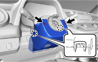
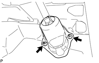
Remove the 2 screws.
Release the tilt lever.
Press both sides of the lower steering column cover to detach the 2 claws.
-
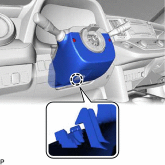
Detach the claw to remove the lower steering column cover.
-
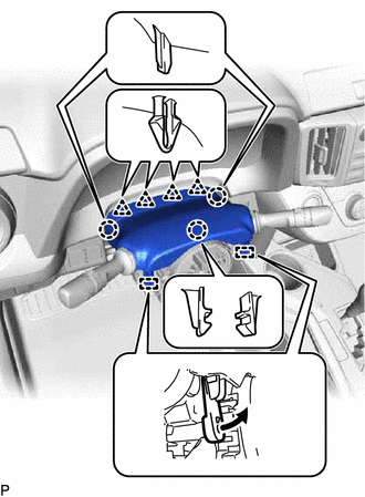
Detach the 3 claws, 4 clips and 2 pins and remove the upper steering column cover.
-
REMOVE COMBINATION SWITCH ASSEMBLY WITH SPIRAL CABLE SUB-ASSEMBLY
Disconnect the connectors from the combination switch assembly with spiral cable sub-assembly.
-
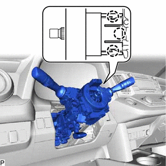
Detach the 3 claws. Remove the combination switch assembly with spiral cable sub-assembly from the steering column assembly.
REMOVE UPPER INSTRUMENT PANEL
REMOVE NO. 1 INSTRUMENT PANEL UNDER COVER SUB-ASSEMBLY
REMOVE NO. 1 LOWER INSTRUMENT PANEL AIRBAG ASSEMBLY
REMOVE COLUMN HOLE COVER SILENCER SHEET
-
Fold back the floor carpet, and then remove the 2 clips and column hole cover silencer sheet.
-
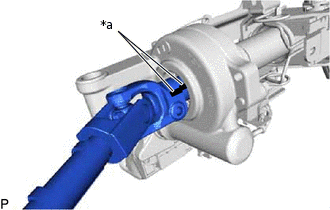
DISCONNECT NO. 2 STEERING INTERMEDIATE SHAFT ASSEMBLY
-
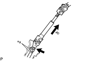
*a
Matchmark
*b
Slide
Place matchmarks on the steering intermediate shaft and No. 2 steering intermediate shaft assembly.
Remove the bolt.
Disconnect the No. 2 steering intermediate shaft assembly from the steering intermediate shaft assembly.
-
REMOVE ELECTRIC POWER STEERING COLUMN SUB-ASSEMBLY
-
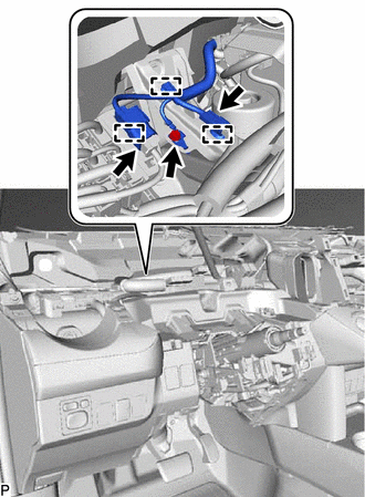
Disconnect the 2 connectors and 3 clamps.
Remove the bolt and disconnect the harness cable.
-
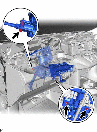
Remove the bolt, 2 nuts and steering column assembly.
Note:Do not release the tilt lever when the steering column assembly is not installed to the vehicle.
Do not drop or strike the steering column assembly. If dropped or struck, replace it with a new one.
-
REMOVE NO. 2 STEERING INTERMEDIATE SHAFT ASSEMBLY
Remove the bolt.
Note:Do not remove the No. 2 steering intermediate shaft assembly from the steering column assembly.
-
*a
Matchmark
Put matchmarks on the No. 2 steering intermediate shaft assembly and steering column assembly.
Remove the No. 2 steering intermediate shaft assembly from the steering column assembly.