ROOM TEMPERATURE SENSOR REMOVAL
PROCEDURE
-
PRECAUTION
Note
After turning the power switch off, waiting time may be required before disconnecting the cable from the negative (-) auxiliary battery terminal. Therefore, make sure to read the disconnecting the cable from the negative (-) auxiliary battery terminal notices before proceeding with work Click here.
-
REMOVE DECK BOARD ASSEMBLY
-
REMOVE NO. 1 DECK BOARD
-
REMOVE NO. 2 DECK BOARD
-
REMOVE REAR DECK FLOOR BOX
-
REMOVE DECK FLOOR BOX RH
-
DISCONNECT CABLE FROM NEGATIVE AUXILIARY BATTERY TERMINAL
Note
When disconnecting the cable, some systems need to be initialized after the cable is reconnected Click here.
-
REMOVE INTEGRATION CONTROL AND PANEL
-
REMOVE UPPER INSTRUMENT PANEL FINISH PANEL
-
REMOVE COOLER THERMISTOR (ROOM TEMPERATURE SENSOR)
-
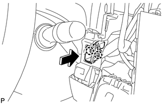
Disengage the 2 claws as shown in the illustration.
-
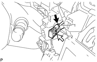
Text in Illustration *1 Connector *2 Aspirator Disconnect the aspirator and connector, and remove the cooler thermistor (room temperature sensor).
-