EXHAUST MANIFOLD INSTALLATION
PROCEDURE
INSTALL NO. 2 EXHAUST MANIFOLD HEAT INSULATOR
Install the No. 2 exhaust manifold heat insulator with the 2 bolts.
13.5 N*m
138 kgf*cm
10 ft.*lbf
INSTALL EXHAUST MANIFOLD CONVERTER SUB-ASSEMBLY
Install a new exhaust manifold to head gasket to the cylinder head sub-assembly.
Temporarily install the exhaust manifold converter sub-assembly with the 5 nuts.
Temporarily install the manifold stay and No. 2 manifold stay with the 2 bolts and 2 nuts.
-
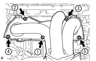
Tighten the 5 nuts in the order shown in the illustration.
35 N*m
357 kgf*cm
26 ft.*lbf
INSTALL MANIFOLD STAY
-
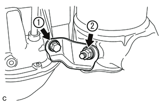
Tighten the bolt and nut in the order shown in the illustration.
43 N*m
438 kgf*cm
32 ft.*lbf
-
INSTALL NO. 2 MANIFOLD STAY
-
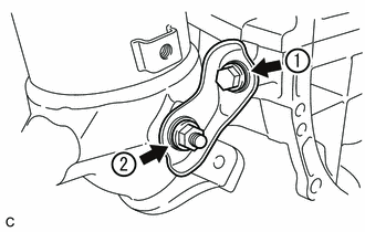
Tighten the bolt and nut in the order shown in the illustration.
43 N*m
438 kgf*cm
32 ft.*lbf
-
INSTALL NO. 2 EGR PIPE (w/ EGR System)
Install 2 new gaskets to the No. 2 EGR pipe.
Note:Make sure the claws of the gasket face the No. 2 EGR pipe.
Install the No. 2 EGR pipe with the 2 bolts and 2 nuts.
36 N*m
367 kgf*cm
27 ft.*lbf
INSTALL NO. 1 MANIFOLD CONVERTER INSULATOR
Install the No. 1 manifold converter insulator with the 3 bolts.
13.5 N*m
138 kgf*cm
10 ft.*lbf
INSTALL AIR FUEL RATIO SENSOR
CONNECT INVERTER RESERVE TANK ASSEMBLY
CONNECT WIRE HARNESS
INSTALL NO. 1 EXHAUST MANIFOLD HEAT INSULATOR
Install the No. 1 exhaust manifold heat insulator with the 4 bolts.
12 N*m
122 kgf*cm
9 ft.*lbf
INSTALL FRONT EXHAUST PIPE ASSEMBLY
-
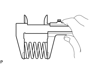
Using a vernier caliper, measure the free length of the compression spring.
Minimum length
41.5 mm (1.63 in.)
If the length is less than the minimum, replace the compression spring.
Using a wire brush, remove any foreign matter from the gasket installation surface.
-
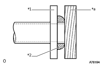
*1
Exhaust Manifold Converter Sub-assembly
*2
Gasket
*a
Wooden Block
Using a plastic-faced hammer and wooden block, tap in a new gasket until its surface is flush with the exhaust manifold converter sub-assembly.
Note:Be sure to install the gasket so that it faces the correct direction.
Do not reuse the gasket.
Do not damage the gasket.
When connecting the front exhaust pipe assembly, do not push in the gasket with the front exhaust pipe assembly.
Install a new gasket to the front exhaust pipe assembly.
-
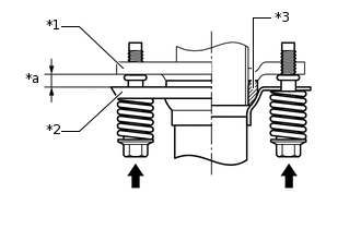
*1
Exhaust Manifold Converter Sub-assembly
*2
Front Exhaust Pipe Assembly
*3
Gasket
*a
Space between flanges: 8.5 mm (0.335 in.)
Install the front exhaust pipe assembly with the 2 compression springs and 4 bolts.
43 N*m
438 kgf*cm
32 ft.*lbf
Tip:After installation, check that the space between the flanges of the exhaust manifold converter sub-assembly and front exhaust pipe assembly is consistent front-to-rear and left-to-right.
Connect the heated oxygen sensor connector.
-
INSTALL NO. 1 ENGINE UNDER COVER
INSTALL NO. 1 ENGINE COVER SUB-ASSEMBLY
INSPECT FOR EXHAUST GAS LEAK