COMMON RAIL INSTALLATION
CAUTION / NOTICE / HINT
Always be sure to check the tightening torque.
If the pressure lines are leaking after installation, they must be replaced.
Do not overtighten the pressure lines.
PROCEDURE
INSTALL PRESSURE DISCHARGE VALVE
INSTALL FUEL PRESSURE SENSOR
INSTALL COMMON RAIL ASSEMBLY
Install the common rail assembly to the cylinder head cover sub-assembly.
Using an E10 "TORX" socket wrench, install the 2 common rail assembly brackets with the 4 bolts.
Tip:Refer to "SPECIFICATIONS - STANDARD BOLT" for the tightening torque.
Connect the fuel return tube.
Connect the pressure discharge valve connector.
Connect the fuel pressure sensor connector.
INSTALL FUEL INLET PIPE SUB-ASSEMBLY
Note:If the pressure lines are leaking after installation, they must be replaced.
Do not overtighten the pressure lines.
-
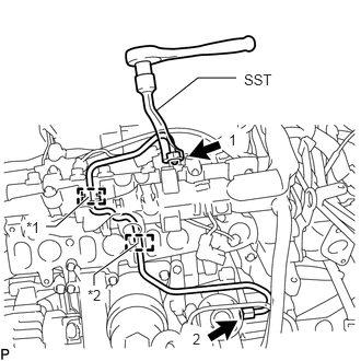
Install the fuel inlet pipe sub-assembly to the rubber grommet and rubber mount as shown in the illustration.
Table 1. Text in Illustration *1
Rubber Grommet
*2
Rubber Mount
Note:Install the rubber mount and rubber grommet at the correct positions on the pressure line.
Temporarily install the union nut at the fuel supply pump assembly end and common rail assembly end of the fuel inlet pipe sub-assembly by hand.
Using SST, tighten the union nut at the fuel supply pump assembly end and common rail assembly end of the fuel inlet pipe sub-assembly as shown in the illustration.
SST
PZ4TB-04959-10
24 N*m
245 kgf*cm
18 ft.*lbf
Note:Reset SST in a timely manner to prevent bending of pressure lines.
INSTALL INJECTION PIPE SUB-ASSEMBLY
INSTALL INTAKE MANIFOLD
INSPECT FOR FUEL LEAK