SFI SYSTEM, Diagnostic DTC:C1476 and C1477
| DTC Code | DTC Name |
|---|---|
| C1476 | Brake Booster Pressure Sensor Circuit Low |
| C1477 | Brake Booster Pressure Sensor Circuit High |
DESCRIPTION
The ECM detects changes in the brake booster assembly pressure based on the voltage signal received from the vacuum sensor assembly installed to the brake booster assembly. If the ECM determines that there is a malfunction in the signal sent by the vacuum sensor assembly, it stores DTC C1476 or C1477.
DTC No. |
Detection Item |
DTC Detection Condition |
Trouble Area |
MIL |
Memory |
|---|---|---|---|---|---|
C1476 |
Brake Booster Pressure Sensor Circuit Low |
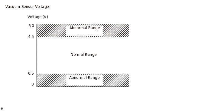
The vacuum sensor assembly output voltage is 0.5 V or less for 1.2 seconds or more (1 trip detection logic). |
|
Does not come on |
DTC stored |
C1477 |
Brake Booster Pressure Sensor Circuit High |
The vacuum sensor assembly output voltage is 4.5 V or higher for 1.2 seconds or more (1 trip detection logic). |
|
Does not come on |
DTC stored |
When any of these DTCs are output, check the brake booster pressure by using the GTS. Enter the following menus: Powertrain / Engine and ECT / Data List / All Data / Brake Boost Pressure Sensor.
Brake Boost Pressure Sensor (V) |
Malfunction |
|---|---|
0.5 or less |
|
4.5 or higher |
|
MONITOR DESCRIPTION
If there is a defect or an open or short circuit in the vacuum sensor assembly, the voltage level deviates from the normal operating range. The ECM interprets this deviation as a malfunction in the vacuum sensor assembly circuit and stores a DTC.
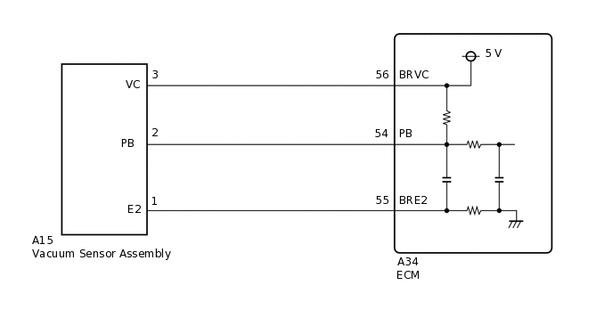
WIRING DIAGRAM
CONFIRMATION DRIVING PATTERN
DTC C1476 and C1477 are detected when the engine idles for 10 seconds or more.
CAUTION / NOTICE / HINT
Read freeze frame data using the GTS. The ECM records vehicle and driving condition information as freeze frame data the moment a DTC is stored. When troubleshooting, freeze frame data can help determine if the vehicle was moving or stationary, if the engine was warmed up or not, if the air fuel ratio was lean or rich, and other data from the time the malfunction occurred.
PROCEDURE
CHECK HARNESS AND CONNECTOR (VACUUM SENSOR ASSEMBLY - ECM)
Disconnect the vacuum sensor assembly connector.
Disconnect the ECM connector.
Measure the resistance according to the value(s) in the table below.
Standard Resistance
Tester Connection
Condition
Specified Condition
A15-3 (VC) - A34-56 (BRVC)
Always
Below 1 Ω
A15-2 (PB) - A34-54 (PB)
Always
Below 1 Ω
A15-1 (E2) - A34-55 (BRE2)
Always
Below 1 Ω
A15-3 (VC) or A34-56 (BRVC) - Body ground and other terminals
Always
10 kΩ or higher
A15-2 (PB) or A34-54 (PB) - Body ground and other terminals
Always
10 kΩ or higher
A15-1 (E2) or A34-55 (BRE2) - Body ground and other terminals
Always
10 kΩ or higher
Result
Proceed to
OK
NG
NG REPAIR OR REPLACE HARNESS OR CONNECTOR
CHECK TERMINAL VOLTAGE (POWER SOURCE OF VACUUM SENSOR ASSEMBLY)
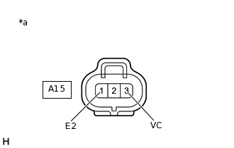
*a
Front view of wire harness connector
(to Vacuum Sensor Assembly)
Disconnect the vacuum sensor assembly connector.
Turn the ignition switch to ON.
Measure the voltage according to the value(s) in the table below.
Standard Voltage
Tester Connection
Condition
Specified Condition
A15-3 (VC) - A15-1 (E2)
Ignition switch ON
4.75 to 5.25 V
Result
Proceed to
OK
NG