SUSPENSION CONTROL SYSTEM PRECAUTION
-
WHEN USING JACK OR LIFT
-
When lifting or jacking up the vehicle, first turn off the vehicle height control.
-
When Using the GTS:
-
Connect the GTS to the DLC3 with the engine switch off.
-
Turn the engine switch on (IG).
-
Turn the GTS on and enter the following menus: Chassis / Air suspension / Utility / Height Control Prohibition Switch.
Chassis > Air suspension > UtilityTester Display Height Control Prohibition Switch -
Operate the vehicle height control prohibition switch according to the instructions on the GTS.
-
-
When Not Using the GTS:
-
Check the ON/OFF setting before operating the vehicle height control switch.
-
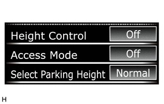
Switch the vehicle height control to OFF via the vehicle settings on the multi-information display.
-
After finishing work, return the setting to its default value.
-
-
-
DISCONNECT AND CONNECT HEIGHT CONTROL TUBE
-
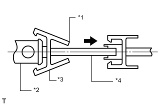
*1 "A" *2 Housing *3 No. 1 Connector *4 Height Control Tube Disconnect the height control tube.
-
for Except Front Pneumatic Cylinder:
Pinch "A" to disconnect the No. 1 connector and pull it out from the housing.
-
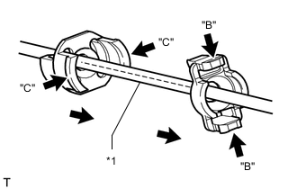
*1 Height Control Tube for Front Pneumatic Cylinder:
Pinch "B" to disconnect the holder air connector clip and pull it out from the No. 1 connector. Pinch "C" to disconnect the No. 1 connector and pull it out from the housing.
-
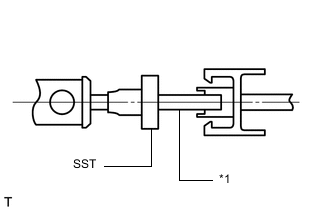
*1 Height Control Tube Set SST to the tube.
- SST
- 09730-00020
-
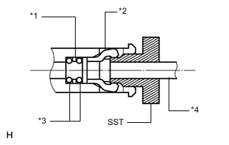
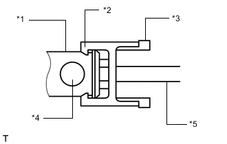
*1 Plate *2 No. 2 Connector *3 O-ring *4 Height Control Tube Insert SST into the housing to expand the claw of the plug or tube connector in the housing.
-
Pull out the tube with SST inserted.
Note
Do not force the tube.
-
Insert a screwdriver into the circular hole on the housing, and remove the No. 2 connector, 2 O-rings and plate from the housing.
Tech Tips
The O-rings, plate and No. 2 connector are nonreusable parts.
-
-
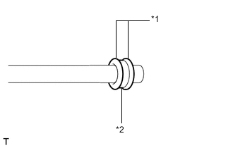
*1 O-ring *2 Plate Install 2 new O-rings and a new plate.
Note
When replacing the parts onto which the tube is to be installed with new ones, it is not necessary to perform this installation procedure.
-
Apply MP grease to 2 new O-rings and a new plate, and then install them to a straight tube.
Note
-
Install the plate between the O-rings.
-
Air leaks may occur if dust or foreign objects come into contact with the O-rings.
-
-
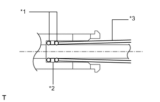
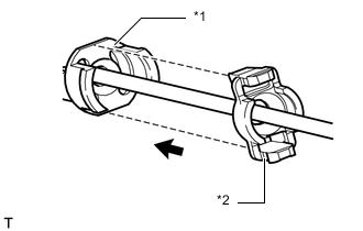
*1 O-ring *2 Plate *3 Cardboard Insert the tube onto which the 2 O-rings and plate are installed into the housing, and then lightly push them in with a piece of rolled up cardboard or equivalent.
-
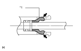
*1 No. 2 Connector Push the No. 2 connector into the housing until a clicking sound is heard.
-
-
*1 Housing *2 Claw *3 No. 1 Connector *4 Port (Hole) *5 Height Control Tube Install the height control tube.
-
Push the height control tube to the housing until a clicking sound is heard.
-
Push the No. 1 connector to the housing until a clicking sound is heard.
Note
-
Turn the claw of the connector 90° so that the claw is aligned with the housing port as shown in the illustration.
-
Lightly pull on the tube to make sure that it is securely connected.
-
-
*1 No. 1 Connector *2 Air Connector Clip Holder for Front Pneumatic Cylinder:
Push the air connector clip holder to the No. 1 connector until a clicking sound is heard.
-
-
-
AIR CHARGING
Note
-
Do not use factory air.
-
In order to prevent the battery from becoming fully depleted, connect the battery charger to the battery when turning the engine switch on (IG) to charge the battery.
-
Keep the power supply connected to prevent the GTS battery from becoming fully depleted.
-
The pressure will change according to the temperature.
Air Refilling Scale Part Dry Air Refilling Scale Not Required 1 Cylinder Equivalent 2 Cylinders Equivalent Tank Equivalent Air Movement
Pattern A
Air Movement
Pattern B
Air Movement
Pattern C
No. 1 Height Control Valve Assembly No. 1 Height Control Valve Sub-assembly ● No. 3 Height control Tube ● No. 8 Height control Tube ● No. 4 Height control Tube ● Height Control Way ● No. 8 Height control Tube ● No. 2 Height Control Valve Assembly No. 2 Height Control Valve Sub-assembly. ● No. 6 Height control Tube ● No. 7 Height control Tube ● No. 9 Height control Tube ● Pneumatic Tank with Tube Assembly Pneumatic Tank Assembly *1, *6 ● Height Control Pressure Sensor *1, *6 ● No. 5 Height control Tube *1, *6 ● w/o Relay Compressor and Dryer Assembly No. 1 Height Control Compressor *2 ● No. 3 Height Control Valve Assembly *1, *2 ● Front Pneumatic Cylinder with Shock Absorber Assembly RH
*2, *3, *4, *5
● ● Front Pneumatic Cylinder with Shock Absorber Assembly LH
*2, *3, *4, *5
● Rear Pneumatic Cylinder with Shock Absorber Assembly RH
*2, *3, *4, *5
● ● Rear Pneumatic Cylinder with Shock Absorber Assembly LH
*2, *3, *4, *5
● *1: Before removing a part, discharge the dry air inside the pneumatic tank assembly via the service valve.
*2: When replacing 1 pneumatic tank assembly, select pattern A before working.
*3: When replacing 2 pneumatic tank assemblies, select pattern B before working.
*4: When replacing 4 pneumatic tank assemblies, perform pattern B two times before working.
*5: Select pattern B when replacing the left and right cylinders on the front or rear side simultaneously.
*6: Nitrogen filling work is only required for pattern C.
-
Pattern A:
Tech Tips
Check each part and system if an error is displayed for air movement pattern A.
-
Connect the GTS to the DLC3 with the engine switch off.
-
Turn the engine switch on (IG).
-
Turn the GTS on and enter the following menus: Chassis / Air suspension / Utility / Air Transfer Pattern A.
Chassis > Air suspension > UtilityTester Display Air Transfer Pattern A -
Perform the air movement and air charging procedures according to the instructions on the GTS.
-
-
Pattern B:
Tech Tips
Check each part and system if an error is displayed for air movement pattern B.
-
Connect the GTS to the DLC3 with the engine switch off.
-
Turn the engine switch on (IG).
-
Turn the GTS on and enter the following menus: Chassis / Air suspension / Utility / Air Transfer Pattern B.
Chassis > Air suspension > UtilityTester Display Air Transfer Pattern B -
Perform the air movement and air charging procedures according to the instructions on the GTS.
-
-
Pattern C:
Tech Tips
Check each part and system if an error is displayed for air movement pattern C.
-
Remove the luggage compartment floor mat.
-
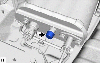
Remove the service valve cap.
-
Select an adapter (SST) that matches the standard of the nitrogen cylinder and install it.
- SST
- 09761-05040 (DIN)
- 09761-05050 (CGA)
- 09761-05060 (BS)
- 09761-05070 (NF)
Tech Tips
The adapter (SST) is not required for JIS standard.
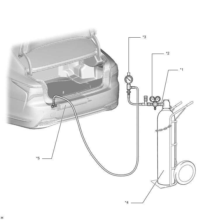
*1 Adapter (SST) *2 Nitrogen Gas Injector (SST) *3 Gauge (SST) *4 Nitrogen Cylinder *5 Pneumatic Tank with Tube Assembly - - -
Connect the nitrogen gas injector (SST) to the adapter (SST) connected to the nitrogen cylinder.
- SST
- 09761-50010
-
Connect the gauge (SST) to the nitrogen gas injector (SST) and pneumatic tank assembly.
Note
Make sure the valve of the gauge (SST) is closed.
-
Connect the GTS to the DLC3 with the engine switch off.
-
Turn the engine switch on (IG).
-
Turn the GTS on and enter the following menus: Chassis / Air suspension / Utility / Air Transfer Pattern C.
Chassis > Air suspension > UtilityTester Display Air Transfer Pattern C -
Perform nitrogen refilling work according to the instructions of the GTS.
-
Install the service valve cap.
-
Install the luggage compartment floor mat.
-
-
Check vehicle height.
-
Adjust vehicle height.
-
-
CONNECTIONS OF TUBES FOR AIR LEAKAGE
Note
When disconnecting the height control tube, be sure to check for air leaks.