AIR CONDITIONING SYSTEM (for Automatic Air Conditioning System), Diagnostic DTC:43
| DTC Code | DTC Name |
|---|---|
| 43 | Air Outlet Damper Control Servo Motor Circuit |
DESCRIPTION
The mode damper servo sub-assembly sends pulse signals to inform the air conditioning amplifier assembly of the mode damper position. The air conditioning amplifier assembly activates the motor (normal or reverse) based on the signals to move the mode damper to any position, which controls the mode changes.
Tech Tips
This DTC is also output if the mode damper and damper link are malfunctioning or unable to move properly. When this DTC is output, confirm that the mechanical parts of the mode damper and damper link are not defective or damaged.
| DTC Code | Detection Item | Trouble Area |
|---|---|---|
| 43 | The mode damper position does not change when the air conditioning amplifier assembly operates the mode damper servo sub-assembly. |
|
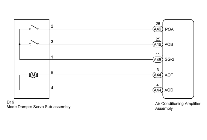
WIRING DIAGRAM
INSPECTION PROCEDURE
Note
When DTC 41, 42 and 43 are output at same time, there would be malfunctioning on power source circuit Click here.
PROCEDURE
-
PERFORM ACTUATOR CHECK
-
Warm up the engine.
-
Enter actuator check mode Click here.
-
Place your hand in front of a vent and check that the mode damper position changes according to the display code.
Display Code Mode Damper Position 0 FACE 1 FACE 2 FACE 3 FACE 4 FACE 5 BI-LEVEL 6 FOOT 7 FOOT 8 FOOT/DEF 9 DEF OK Mode damper position changes in accordance with each display code. Tech Tips
The progression through the steps of the actuator check can be changed from automatic to manual by pressing the front DEF switch.
Result Result Proceed to OK (When troubleshooting according to problem symptoms table.) A OK (When troubleshooting according to DTC.) B NG C
B 
REPLACE AIR CONDITIONING AMPLIFIER ASSEMBLY Click here
C 
CHECK HARNESS AND CONNECTOR (MODE DAMPER SERVO - AIR CONDITIONING AMPLIFIER) Click here
A 
PROCEED TO NEXT SUSPECTED AREA SHOWN IN PROBLEM SYMPTOMS TABLE Click here
-
-
CHECK HARNESS AND CONNECTOR (MODE DAMPER SERVO - AIR CONDITIONING AMPLIFIER)
-
Disconnect the D16 mode damper servo sub-assembly connector.
-
Disconnect the A44 and A46 air conditioning amplifier assembly connectors.
-
Measure the resistance according to the value(s) in the table below.
Standard Resistance Tester Connection Condition Specified Condition D16-4 - A44-4 (AOD) Always Below 1 Ω D16-5 - A44-3 (AOF) D16-2 - A46-26 (POA) D16-3 - A46-25 (POB) D16-1 - A46-11 (SG-2) D16-4 - Body ground Always 10 kΩ or higher D16-5 - Body ground D16-2 - Body ground D16-3 - Body ground D16-1 - Body ground
NG
REPAIR OR REPLACE HARNESS OR CONNECTOR
OK 
-
-
REPLACE MODE DAMPER SERVO SUB-ASSEMBLY
-
Temporally replace the mode damper servo sub-assembly with a new or normally functioning one Click here.
-
Check the mode damper operates normally.
OK Mode damper operates normally.
NG
REPLACE AIR CONDITIONING AMPLIFIER ASSEMBLY Click here
OK
END (MODE DAMPER SERVO IS DEFECTIVE)
-