LANE DEPARTURE ALERT SYSTEM TERMINALS OF ECU
-
CHECK LANE DEPARTURE WARNING CAMERA

Terminal No. (Symbol) Wiring Color Terminal Description Condition Specified Condition U13-4 (LKSW) - U13-11 (GND) Y - W-B Lane departure alert main switch Power switch on (IG), lane departure alert main switch (integration control and panel assembly) off 4 V or higher U13-4 (LKSW) - U13-11 (GND) Y - W-B Lane departure alert main switch Power switch on (IG), lane departure alert main switch (integration control and panel assembly) on Below 1 V U13-6 (CA1P) - U13-11 (GND) B - W-B CAN communication signal Power switch on (IG) Pulse generation
(Waveform 1)
U13-7 (IGB) - U13-11 (GND) V - W-B Power source Power switch on (IG) 11 to 14 V U13-11 (GND) - Body ground W-B - Body ground Ground Always Below 1 Ω U13-12 (CA1N) - U13-11 (GND) W - W-B CAN communication signal Power switch on (IG) Pulse generation
(Waveform 1)
If the result is not as specified, there may be a malfunction on the wire harness side.
Tech Tips
Oscilloscope waveform samples are provided here for reference only. Noise and fluctuating waveforms have been omitted.
-
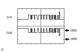
Waveform 1 (CAN communication signal)
Item Content Terminal Name CH1: U13-6 (CA1P) - U13-11 (GND)
CH2: U13-12 (CA1N) - U13-11 (GND)
Tester Range 1 V/DIV., 50 μs./DIV. Condition Power switch on (IG) Tech Tips
The waveform will vary depending on the content of the digital communication (digital signal).
-