STEERING GEAR INSTALLATION

PROCEDURE
-
INSTALL TIE ROD END SUB-ASSEMBLY LH
-
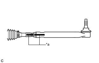
Text in Illustration *a Matchmark Install the lock nut and tie rod end sub-assembly LH to the steering gear assembly until the matchmarks are aligned.
Tech Tips
After adjusting the toe-in, tighten the lock nut.
-
-
INSTALL TIE ROD END SUB-ASSEMBLY RH
Tech Tips
Perform the same procedure as for the LH side.
-
INSTALL STEERING LINK ASSEMBLY
-
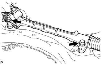
Install the steering link assembly to the front suspension crossmember sub-assembly with the 2 bolts and 2 nuts.
- Torque:
- 110 N*m { 1122 kgf*cm, 81 ft.*lbf }
Note
-
Keep the nut from rotating while turning the bolt because the nut has its own stopper.
-
Make sure to tighten the bolts starting from the left side of the vehicle.
-
-
INSTALL STEERING INTERMEDIATE SHAFT
-
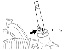
Text in Illustration *a Matchmark Align the matchmarks and install the steering intermediate shaft to the steering link assembly.
-
Install the bolt.
- Torque:
- 35 N*m { 357 kgf*cm, 26 ft.*lbf }
-
-
INSTALL NO. 1 STEERING COLUMN HOLE COVER SUB-ASSEMBLY
-
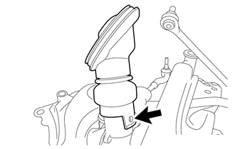
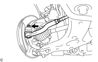
Align the round hole in the No. 1 steering column hole cover sub-assembly with the protrusion of the steering link assembly to install the cover.
-
-
INSTALL FRONT SUSPENSION CROSSMEMBER SUB-ASSEMBLY
-
INSTALL FRONT SUSPENSION MEMBER REAR BRACE LH
-
INSTALL FRONT SUSPENSION MEMBER REAR BRACE RH
Tech Tips
Perform the same procedure as for the LH side.
-
INSTALL REAR SIDE RAIL REINFORCEMENT SUB-ASSEMBLY LH
-
INSTALL REAR SIDE RAIL REINFORCEMENT SUB-ASSEMBLY RH
Tech Tips
Perform the same procedure as for the LH side.
-
INSTALL FRONT ENGINE MOUNTING BRACKET LOWER REINFORCEMENT
-
CONNECT FRONT LOWER NO. 1 SUSPENSION ARM SUB-ASSEMBLY LH
-
CONNECT FRONT LOWER NO. 1 SUSPENSION ARM SUB-ASSEMBLY RH
Tech Tips
Perform the same procedure as for the LH side.
-
CONNECT TIE ROD END SUB-ASSEMBLY LH
-
Connect the tie rod end sub-assembly LH to the steering knuckle with the nut.
- Torque:
- 49 N*m { 500 kgf*cm, 36 ft.*lbf }
Note
Further tighten the nut up to 60° if the holes for the cotter pin are not aligned.
-
Install a new cotter pin.
-
-
CONNECT TIE ROD END SUB-ASSEMBLY RH
Tech Tips
Perform the same procedure as for the LH side.
-
INSTALL FRONT STABILIZER LINK ASSEMBLY LH
-
INSTALL FRONT STABILIZER LINK ASSEMBLY RH
Tech Tips
Perform the same procedure as for the LH side.
-
CONNECT NO. 1 STEERING COLUMN HOLE COVER SUB-ASSEMBLY
-
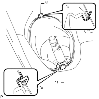
Text in Illustration *1 Clip A *2 Clip B *a Lip Place clip A as shown in the illustration and engage clip B to the body to connect the No. 1 steering column hole cover sub-assembly.
Note
Make sure that the lip of the No. 1 steering column hole cover sub-assembly is not damaged.
-
-
CONNECT NO. 2 STEERING INTERMEDIATE SHAFT ASSEMBLY
-
INSTALL COLUMN HOLE COVER SILENCER SHEET
-
INSTALL REAR ENGINE UNDER COVER LH
-
INSTALL REAR ENGINE UNDER COVER RH
-
INSTALL FRONT NO. 3 ENGINE UNDER COVER
-
INSTALL NO. 2 ENGINE UNDER COVER
-
INSTALL NO. 1 ENGINE UNDER COVER
-
INSTALL FRONT WHEELS
- Torque:
- 103 N*m { 1050 kgf*cm, 76 ft.*lbf }
-
STABILIZE SUSPENSION
-
INSPECT AND ADJUST FRONT WHEEL ALIGNMENT