NAVIGATION SYSTEM(for HDD) Microphone Circuit between Microphone and Navigation ECU
| DTC Code | DTC Name |
|---|---|
| Microphone Circuit between Microphone and Navigation ECU |
DESCRIPTION
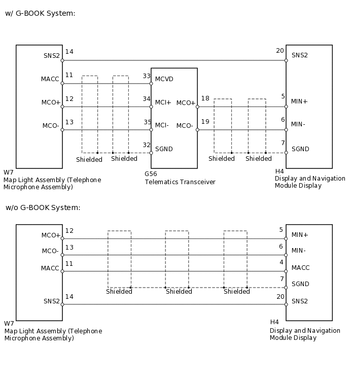
w/ G-BOOK System
Using this circuit, the telematics transceiver sends power to the map light assembly (telephone microphone assembly), and the map light assembly (telephone microphone assembly) sends microphone signals to the display and navigation module display via the telematics transceiver. The display and navigation module display and map light assembly (telephone microphone assembly) are connected to each other using the microphone connection detection signal lines.
w/o G-BOOK System
Using this circuit, the display and navigation module display sends power to the map light assembly (telephone microphone assembly), and the map light assembly (telephone microphone assembly) sends microphone signals to the display and navigation module display. The display and navigation module display and map light assembly (telephone microphone assembly) are connected to each other using the microphone connection detection signal lines.
WIRING DIAGRAM
PROCEDURE
INSPECT DISPLAY AND NAVIGATION MODULE DISPLAY
-
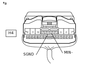
*a
Component with harness connected
(Display and Navigation Module Display)
Measure the resistance according to the value(s) in the table below.
Standard Resistance
Tester Connection
Condition
Specified Condition
H4-7 (SGND) - Body ground
Always
Below 1 Ω
H4-6 (MIN-) - Body ground
Always
Below 1 Ω
Result
Result
OK
NG
-
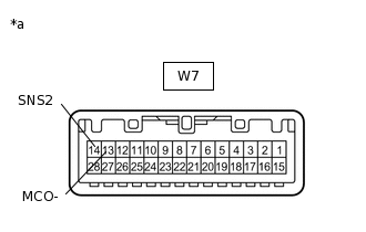
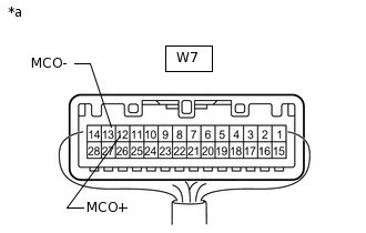
CHECK HARNESS AND CONNECTOR (DISPLAY AND NAVIGATION MODULE DISPLAY - MAP LIGHT ASSEMBLY)
Disconnect the H4 display and navigation module display connector.
Disconnect the W7 map light assembly connector.
Measure the resistance according to the value(s) in the table below.
Standard Resistance
Table 1. w/ G-BOOK System Tester Connection
Condition
Specified Condition
H4-20 (SNS2) - W7-14 (SNS2)
Always
Below 1 Ω
H4-20 (SNS2) - Body ground
Always
10 kΩ or higher
w/o G-BOOK System
Tester Connection
Condition
Specified Condition
H4-5 (MIN+) - W7-12 (MCO+)
Always
Below 1 Ω
H4-6 (MIN-) - W7-13 (MCO-)
Always
Below 1 Ω
H4-4 (MACC) - W7-11 (MACC)
Always
Below 1 Ω
H4-20 (SNS2) - W7-14 (SNS2)
Always
Below 1 Ω
H4-5 (MIN+) - Body ground
Always
10 kΩ or higher
H4-6 (MIN-) - Body ground
Always
10 kΩ or higher
H4-7 (SGND) - Body ground
Always
10 kΩ or higher
H4-4 (MACC) - Body ground
Always
10 kΩ or higher
H4-20 (SNS2) - Body ground
Always
10 kΩ or higher
Result
Result
Proceed to
OK (w/ G-BOOK System)
A
OK (w/o G-BOOK System)
B
NG
C
CHECK HARNESS AND CONNECTOR (DISPLAY AND NAVIGATION MODULE DISPLAY - TELEMATICS TRANSCEIVER)
Disconnect the H4 display and navigation module display connector.
Disconnect the G56 telematics transceiver connector.
Measure the resistance according to the value(s) in the table below.
Standard Resistance
Tester Connection
Condition
Specified Condition
H4-5 (MIN+) - G56-18 (MCO+)
Always
Below 1 Ω
H4-6 (MIN-) - G56-19 (MCO-)
Always
Below 1 Ω
H4-5 (MIN+) - Body ground
Always
10 kΩ or higher
H4-6 (MIN-) - Body ground
Always
10 kΩ or higher
H4-7 (SGND) - Body ground
Always
10 kΩ or higher
Result
Result
OK
NG
NG REPAIR OR REPLACE HARNESS OR CONNECTOR
CHECK HARNESS AND CONNECTOR (TELEMATICS TRANSCEIVER - MAP LIGHT ASSEMBLY)
Disconnect the G56 telematics transceiver connector.
Disconnect the W7 map light assembly connector.
Measure the resistance according to the value(s) in the table below.
Standard Resistance
Tester Connection
Condition
Specified Condition
G56-33 (MCVD) - W7-11 (MACC)
Always
Below 1 Ω
G56-34 (MCI+) - W7-12 (MCO+)
Always
Below 1 Ω
G56-35 (MCI-) - W7-13 (MCO-)
Always
Below 1 Ω
G56-33 (MCVD) - Body ground
Always
10 kΩ or higher
G56-34 (MCI+) - Body ground
Always
10 kΩ or higher
G56-35 (MCI-) - Body ground
Always
10 kΩ or higher
G56-32 (SGND) - Body ground
Always
10 kΩ or higher
Result
Result
OK
NG
NG REPAIR OR REPLACE HARNESS OR CONNECTOR
CHECK TELEMATICS TRANSCEIVER
-
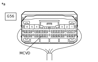
*a
Component with harness connected
(Telematics Transceiver)
Measure the voltage according to the value(s) in the table below.
Standard Voltage
Tester Connection
Switch Condition
Specified Condition
G56-33 (MCVD) - Body ground
Engine switch on (ACC)
4 to 6 V
Result
Result
OK
NG
-
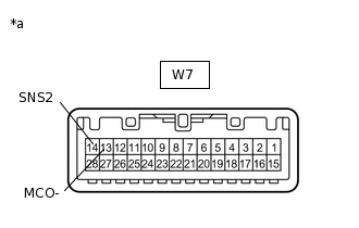
INSPECT MAP LIGHT ASSEMBLY
Remove the map light assembly
-
Measure the resistance according to the value(s) in the table below.
Standard Resistance
Tester Connection
Condition
Specified Condition
14 (SNS2) - 13 (MCO-)
Always
Below 1 Ω
Result
Result
OK
NG
NG REPLACE TELEPHONE MICROPHONE ASSEMBLYClick here
CHECK MAP LIGHT ASSEMBLY
-
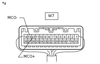
*a
Component with harness connected
(Map Light Assembly)
Connect an oscilloscope to terminals W7-12 (MCO+) and W7-13 (MCO-) of the telephone microphone assembly connector.
Turn the engine switch on (ACC).
Check the waveform of the telephone microphone assembly using the oscilloscope.
Result
Result
Proceed to
Waveform synchronized with the voice input to the map light assembly is output
A
Waveform synchronized with the voice input to the map light assembly is not output
B
-
REPLACE TELEPHONE MICROPHONE ASSEMBLY
Replace the telephone microphone assembly
Check if the same malfunction recurs.
Result
Result
Proceed to
Malfunction does not recur (returns to normal)
A
Malfunction recurs
B
A END
CHECK DISPLAY AND NAVIGATION MODULE DISPLAY
-
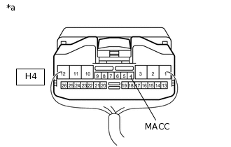
*a
Component with harness connected
(Display and Navigation module Display)
Measure the voltage according to the value(s) in the table below.
Standard Voltage
Tester Connection
Switch Condition
Specified Condition
H4-4 (MACC) - Body ground
Engine switch on (ACC)
4 to 6 V
Result
Result
OK
NG
-
INSPECT MAP LIGHT ASSEMBLY
Remove the map light assembly
-
Measure the resistance according to the value(s) in the table below.
Standard Resistance
Tester Connection
Condition
Specified Condition
14 (SNS2) - 13 (MCO-)
Always
Below 1 Ω
Result
Result
OK
NG
NG REPLACE TELEPHONE MICROPHONE ASSEMBLYClick here
CHECK MAP LIGHT ASSEMBLY
-
*a
Component with harness connected
(Map Light Assembly)
Connect an oscilloscope to terminals W7-12 (MCO+) and W7-13 (MCO-) of the telephone microphone assembly connector.
Turn the engine switch on (ACC).
Check the waveform of the telephone microphone assembly using the oscilloscope.
Result
Result
Proceed to
Waveform synchronized with the voice input to the map light assembly is output
A
Waveform synchronized with the voice input to the map light assembly is not output
B
-
REPLACE TELEPHONE MICROPHONE ASSEMBLY
Replace the telephone microphone assembly
Check if the same malfunction recurs.
Result
Result
Proceed to
Malfunction does not recur (returns to normal)
A
Malfunction recurs
B
A END