SFI SYSTEM, Diagnostic DTC:P1612
| DTC Code | DTC Name |
|---|---|
| P1612 | IMMO Short Circuit to Ground or to Batt |
DESCRIPTION
When there is a communication malfunction between the ECM and certification ECU (smart key ECU assembly)*1, ID code box (immobiliser code ECU)*2 or transponder key ECU*3, the ECM stores this DTC.
*1: for LHD (w/ Entry and Start System)
*2: for RHD (w/ Entry and Start System)
*3: w/o Entry and Start System
DTC No. |
Detection Item |
DTC Detection Condition |
Trouble Area |
MIL |
Memory |
|---|---|---|---|---|---|
P1612 |
IMMO Short Circuit to Ground or to Batt |
Open or short in immobiliser (IMI and IMO terminal) system circuit. |
|
Does not Come on |
DTC stored |
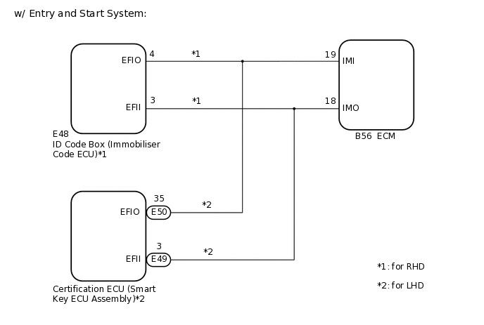
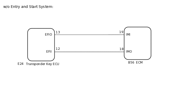
WIRING DIAGRAM
PROCEDURE
CHECK ANY OTHER DTCS OUTPUT (IN ADDITION TO DTC P1612)
Connect the GTS to the DLC3.
Turn the ignition switch to ON.
Turn the GTS on.
Enter the following menus: System Select / Health Check.
Check for DTCs.
Result
Result
Proceed to
DTC P1612 is output (w/ Entry and Start System)
A
DTC P1612 is output (w/o Entry and Start System)
B
DTC P1612 and other DTCs are output
C
Tip:If any DTCs other than P1612 are output, troubleshoot those DTCs first.
CHECK HARNESS AND CONNECTOR (CERTIFICATION ECU (SMART KEY ECU ASSEMBLY) OR ID CODE BOX (IMMOBILISER CODE ECU) - ECM)
Disconnect the certification ECU (smart key ECU assembly) connector (for LHD).
Disconnect the ID code box (immobiliser code ECU) connector (for RHD).
Disconnect the ECM connector.
Measure the resistance according to the value(s) in the table below.
Standard Resistance (for RHD)
Tester Connection
Condition
Specified Condition
E48-4 (EFIO) - B56-19 (IMI)
Always
Below 1 Ω
E48-3 (EFII) - B56-18 (IMO)
Always
Below 1 Ω
E48-4 (EFIO) or B56-19 (IMI) - Body ground and other terminals
Always
10 kΩ or higher
E48-3 (EFII) or B56-18 (IMO) - Body ground and other terminals
Always
10 kΩ or higher
Standard Resistance (for LHD)
Tester Connection
Condition
Specified Condition
E50-35 (EFIO)- B56-19 (IMI)
Always
Below 1 Ω
E49-3 (EFII) - B56-18 (IMO)
Always
Below 1 Ω
E50-35 (EFIO) or B56-19 (IMI) - Body ground and other terminals
Always
10 kΩ or higher
E49-3 (EFII) or B56-18 (IMO) - Body ground and other terminals
Always
10 kΩ or higher
Result
Proceed to
OK
NG
OK CHECK IMMOBILISER SYSTEMClick here
NG REPAIR OR REPLACE HARNESS OR CONNECTOR
CHECK HARNESS AND CONNECTOR (TRANSPONDER KEY ECU - ECM)
Disconnect the transponder key ECU connector.
Disconnect the ECM connector.
Measure the resistance according to the value(s) in the table below.
Standard Resistance
Tester Connection
Condition
Specified Condition
E24-13 (EFIO) - B56-19 (IMI)
Always
Below 1 Ω
E24-12 (EFII) - B56-18 (IMO)
Always
Below 1 Ω
E24-13 (EFIO) or B56-19 (IMI) - Body ground and other terminals
Always
10 kΩ or higher
E24-12 (EFII) or B56-18 (IMO) - Body ground and other terminals
Always
10 kΩ or higher
Result
Proceed to
OK
NG
NG REPAIR OR REPLACE HARNESS OR CONNECTOR
CHECK IMMOBILISER SYSTEM
Check the immobiliser system.
w/ Entry and Start System:Click here
w/o Entry and Start System:Click here
Result
Proceed to
OK
NG
NG REPAIR OR REPLACE IMMOBILISER SYSTEM