CHARGING SYSTEM, Diagnostic DTC:P1602
| DTC Code | DTC Name |
|---|---|
| P1602 | Deterioration of Battery |
DESCRIPTION
The power management control ECU monitors the battery. When the engine is running (not cranking) and the battery voltage drops below a specified level, the ECU determines that there is battery deterioration and stores this DTC.
DTC Code |
DTC Detection Condition |
Trouble Area |
|---|---|---|
P1602 |
Battery capacity is abnormally low for 10 seconds or more when the engine is running (not cranking) (1 trip detection logic). |
|
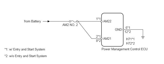
WIRING DIAGRAM
PROCEDURE
CHECK FOR DTC
Connect the GTS to the DLC3.
Turn the ignition switch to ON.
Turn the GTS on.
Check for DTCs (Click here).
Table 1. Result Result
Proceed to
Only DTC P1602 is output.
A
Other DTCs are output in addition to DTC P1602.
B
CHECK CHARGING SYSTEM
Check the charging system (Click here).
Table 2. Result Result
Proceed to
OK
w/ Entry and Start System
A
w/o Entry and Start System
B
NG
C
CHECK HARNESS AND CONNECTOR (POWER SOURCE CIRCUIT)
-
Disconnect the H71 power management control ECU connector.
Measure the voltage according to the value(s) in the table below.
Standard Voltage
Tester Connection
Condition
Specified Condition
H71-2 (AM21) - Body ground
Always
11 to 14 V
H71-1 (AM22) - Body ground
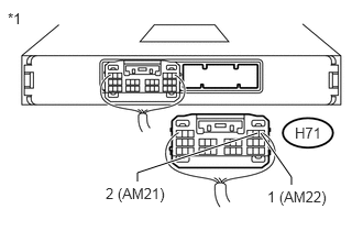
Table 3. Text in Illustration *1
Rear view of wire harness connector
(to Power Management Control ECU)
REPAIR OR REPLACE HARNESS OR CONNECTOR
-
CHECK HARNESS AND CONNECTOR (GROUND CIRCUIT)
Measure the resistance according to the value(s) in the table below.
Standard Resistance
Tester Connection
Condition
Specified Condition
H71-6 (GND) - Body ground
Always
Below 1 Ω
REPAIR OR REPLACE HARNESS OR CONNECTOR
CHECK HARNESS AND CONNECTOR (POWER SOURCE CIRCUIT)
-
Disconnect the H72 power management control ECU connector.
Measure the voltage according to the value(s) in the table below.
Standard Voltage
Tester Connection
Condition
Specified Condition
H72-8 (AM21) - Body ground
Always
11 to 14 V
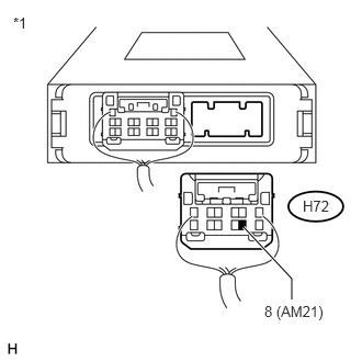
Table 4. Text in Illustration *1
Rear view of wire harness connector
(to Power Management Control ECU)
REPAIR OR REPLACE HARNESS OR CONNECTOR
-
CHECK HARNESS AND CONNECTOR (GROUND CIRCUIT)
Measure the resistance according to the value(s) in the table below.
Standard Resistance
Tester Connection
Condition
Specified Condition
H72-12 (GND) - Body ground
Always
Below 1 Ω
REPAIR OR REPLACE HARNESS OR CONNECTOR