DIFFERENTIAL PRESSURE SENSOR INSTALLATION
-
INSTALL DIFFERENTIAL PRESSURE SENSOR ASSEMBLY
-
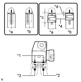
Text in Illustration *1 Marking *2 Green Paint Mark *3 Orange Paint Mark *4 New Clip *a CORRECT *b INCORRECT *c 14.3 mm (0.562 in.) or less *d Clip must not protrude past end of hose Install 2 new clips, the No. 6 exhaust pipe air hose and No. 7 exhaust pipe air hose to the differential pressure sensor.
Tech Tips
-
Connect the air hoses so that the paint marks of the air hoses are as shown in the illustration.
-
Make sure the clips are as shown in the illustration.
-
-
Install the differential pressure sensor with the nut.
- Torque:
- 5.0 N*m { 51 kgf*cm, 44 in.*lbf }
-
for Automatic Transmission:
-
Install the sensor bracket with the bolt.
- Torque:
- 8.0 N*m { 82 kgf*cm, 71 in.*lbf }
-
Attach the 2 clamps and connect the connector.
-
-
for Manual Transmission:
Connect the connector.
-
-
INSTALL NO. 1 FRONT FLOOR HEAT INSULATOR
-
Install the No. 1 front floor heat insulator with the 3 nuts.
- Torque:
- 5.0 N*m { 51 kgf*cm, 44 in.*lbf }
-
-
INSTALL FRONT EXHAUST PIPE ASSEMBLY