AIR CONDITIONING SYSTEM
-
CONSTRUCTION
-
The 7SES17C*1 or 7SAS17C*2 type compressor with pulley assembly is used.
*1: Models with A25A-FKS engine
*2: Models with 2GR-FKS engine
-
These compressor with pulley assemblies are continuously variable capacity type air conditioning compressors. Their capacities can be varied in accordance with the cooling load of the air conditioning system.
-
The 7SES17C type compressor with pulley assembly consists of a pulley, shaft, lug plate, swash plate, piston, shoe, crank chamber, cylinder, solenoid control valve with built-in Crank chamber to Suction passage (CS) valve, oil separator and variable suction side throttle.
-
The 7SAS17C type compressor with pulley assembly consists of a magnet clutch assembly, shaft, lug plate, swash plate, piston, shoe, crank chamber, cylinder, air conditioning lock sensor and solenoid control valve with built-in Crank chamber to Suction passage (CS) valve, oil separator and variable suction side throttle.
-
A plastic Damper Limiter (DL) type pulley is used on models with the A25A-FKS engine and a pulley with a magnetic clutch is used on models with the 2GR-FKS engine.
-
The oil separator consists of an oil separator chamber and an oil separator cylinder.
Figure 1. 7SES17C Type Compressor with Pulley Assembly
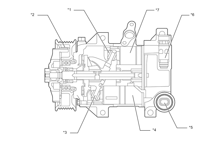
*1 Shoe *2 Plastic Damper Limiter (DL) Pulley *3 Swash Plate *4 Cylinder *5 Ps Control Valve *6 Variable Suction Side Throttle *7 Piston - - Figure 2. 7SAS17C Type Compressor with Pulley Assembly
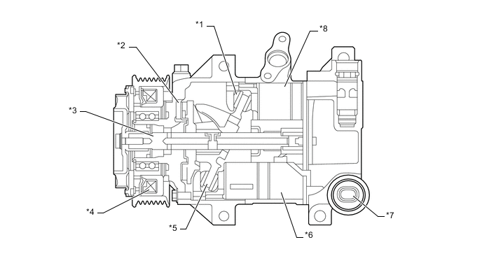
*1 Shoe *2 Lug Plate *3 Shaft *4 Magnet Clutch Assembly *5 Swash Plate *6 Cylinder *7 Solenoid Control Valve *8 Piston -
Structure of external control type continuously variable capacity compressor
-
When the shaft rotates, the swash plate is rotated via the lug plate, which is directly connected to the shaft. This rotational motion of the swash plate is converted to piston movement for introducing, compressing and discharging the refrigerant. Variable control of capacity is to control pressure in the swash plate chamber. This pressure change changes the tilt angle of the swash plate, thereby changing the piston stroke to control the discharge volume of the refrigerant. With the external control type continuously variable capacity compressor, control current applied to the PS control valve is steplessly changed. This allows for a wider range of discharge volume control, contributing to enhanced cabin comfort and reduced energy consumption.
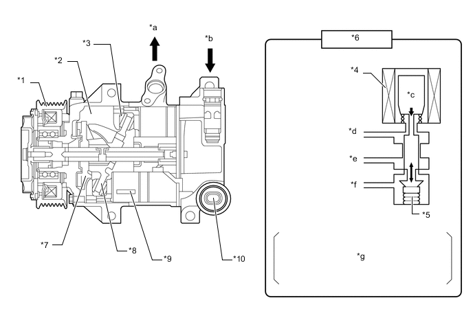
*1 Pulley *2 Swash Plate Chamber *3 Shoe *4 Coil *5 Bellows *6 Ps Control Valve *7 Lug Plate *8 Swash Plate *9 Piston *10 Ps Control Valve *a Discharge Pressure *b Suction Pressure *c Electromagnetic Force *d Suction Pressure (Ps) *e Discharge Pressure (Pd) *f Pressure in Swash Plate Chamber (Pc) *g Based on the duty cycle controlled application of power to the coil in the Ps control valve, electromagnetic force is controlled to expand and compress the bellows, changing the internal pressure of the swash plate. - -
-
-
-
OPERATION
-
External Control Type Continuously Variable Capacity Compressor Operation
-
Operation when capacity increase is necessary
-
If the heat load has been increased or if the volume needs to be increased such as when acceleration control has finished, the current applied to the PS control valve coil is increased. The electromagnetic force will then become larger than the spring force and act in the opposite direction of the coil, closing the Pd to Pc passage. As a result of this, high pressure will be shut off and the pressure in the swash plate chamber will gradually decrease. Therefore, the sum of the pressure applied to the left side of the piston (Pc), spring force (Fs) and reaction force from the lug plate (FL) becomes smaller than the sum of the force applied to the right side of the piston (P1 + ... + P6), and the piston is moved to the left, increasing the tilt angle of the swash plate. This results in larger piston strokes. (The illustration is of when the discharge volume is large.)
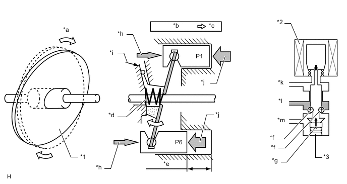
*1 Swash Plate *2 Coil *3 Bellows - - *a Amount of swash plate tilt increases *b Pd to Pc Passage: Opened *c Pc decreased *d Spring (Fs) *e Large stroke *f Pd to Pc Passage (Closed) *g Spring Force *h (Pc+Fs+FL) *i Lug Plate (FL) *j (P1 + ... + P6) *k Suction Pressure (Ps) *l Discharge Pressure (Pd) *m Pressure in Swash Plate Chamber (Pc) - -
-
-
Operation when capacity decrease is necessary
-
If the heat load has been decreased or if the volume needs to be decreased such as when accelerating or driving at high speeds, the current applied to the PS control valve coil is decreased. The electromagnetic force will then become smaller than the spring force and act in the same direction of the coil, opening the Pd to Pc passage. As a result of this, high pressure (Pd) will be introduced into the swash plate chamber and the pressure in the swash plate chamber will gradually increase. Therefore, the sum of the pressure applied to the left side of the piston (Pc), spring force (Fs) and reaction force from the lug plate (FL) becomes larger than the sum of the force applied to the right side of the piston (P1 + ... + P6), and the piston is moved to the right, decreasing the tilt angle of the swash plate. This results in smaller piston strokes. (The illustration is of when the discharge volume is small.)
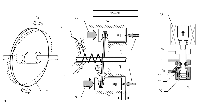
*1 Swash Plate *2 Coil *3 Bellows *4 Piston *a Amount of swash plate tilt increases *b Pd to Pc Passage: Opened *c Pc decreased *d Spring (Fs) *e Large stroke *f Pd to Pc Passage (Closed) *g Spring Force *h (Pc+Fs+FL) *i Lug Plate (FL) *j (P1 + ... + P6) *k Suction Pressure (Ps) *l Discharge Pressure (Pd) *m Pressure in Swash Plate Chamber (Pc) - -
-
-
-
Variable CS Valve
-
The variable capacity compressor sends compressed control gas from the Ps control valve to the swash plate chamber to change the tilt angle of the swash plate, thereby changing the compressor capacity. After control, control gas flows back from the swash plate chamber to the suction chamber, and is then compressed again. Conventionally, the refrigerant was sent back from the swash plate chamber to the suction chamber through a fixed orifice.
-
The variable CS valve is partially closed only when variable operation is performed, which requires control gas, allowing for variable operation using the minimum amount of control gas. By reducing the amount of control gas, compressor power is reduced.
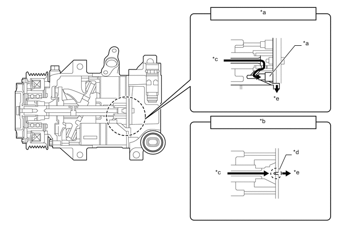
*a Variable CS Valve *b Reference: Fixed Orifice Valve *c from Swash Plate Chamber *d Fixed Orifice Valve *e to Suction Chamber - - 
Control gas - -
-
-
Shaft Oil Separator
-
For the conventional cooler compressor assembly, oil was mixed in with the suction refrigerant to ensure sliding performance of the parts. However, when the refrigerant was discharged from the cooler compressor assembly, oil, which did not contribute to refrigerant efficiency, was circulated in the air conditioning system, adversely affecting the cooling efficiency. For the 7SES17C/7SAS17C type cooler compressor assembly, an oil separator is provided to the shaft so that a large amount of the oil is kept in the cooler compressor assembly. This greatly enhances the cooling performance and helps to reduce the power consumption of the air conditioning system.
-
For the conventional cooler compressor assembly, refrigerant was sent back from the swash plate chamber through the oil return portion, located on the tip of the shaft, to the suction chamber so that oil containing refrigerant gas was sent back to the suction chamber and the amount of circulated oil was increased.
-
For the shaft oil separator, an oil return portion is provided in the area between the swash plate and lug plate, in which a small amount of oil is circulated, in order to send back refrigerant gas containing only a small amount of oil to the suction chamber. This ensures that a large amount of oil is kept in the swash plate chamber, which contains sliding parts, thereby reducing the amount of circulated oil.
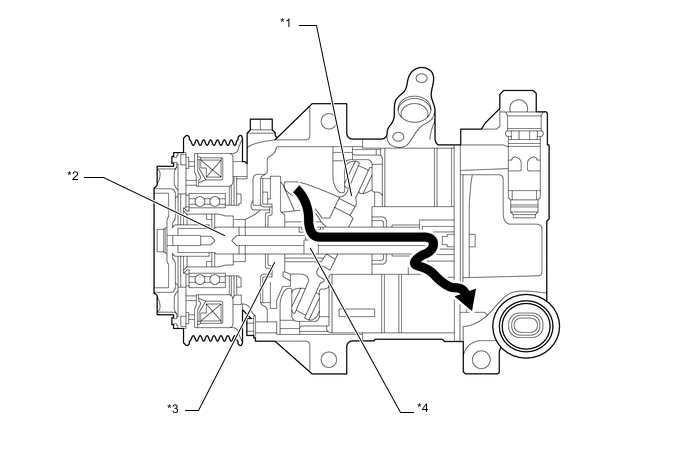
*1 Swash Plate *2 Shaft *3 Lug Plate *4 Shaft Oil Separator Refrigerant gas - -
-
-
Variable Suction Side Valve
-
For the conventional variable suction side compressor, a pulsation dampener was used in the suction passage to counter the suction pulsation noises generated when controlling the refrigerant volume. For the newly adopted cooler compressor assembly, a variable suction side valve, which enables the adjustment of refrigerant flow in the suction passage is used. This valve is closed in accordance with the refrigerant flow when controlling the refrigerant volume, helping to reduce suction pulsation noises. Also, with the maximum volume of refrigerant, the variable suction side valve is fully opened to prevent the suction resistance of the cooler compressor assembly from being increased due to the throttle.
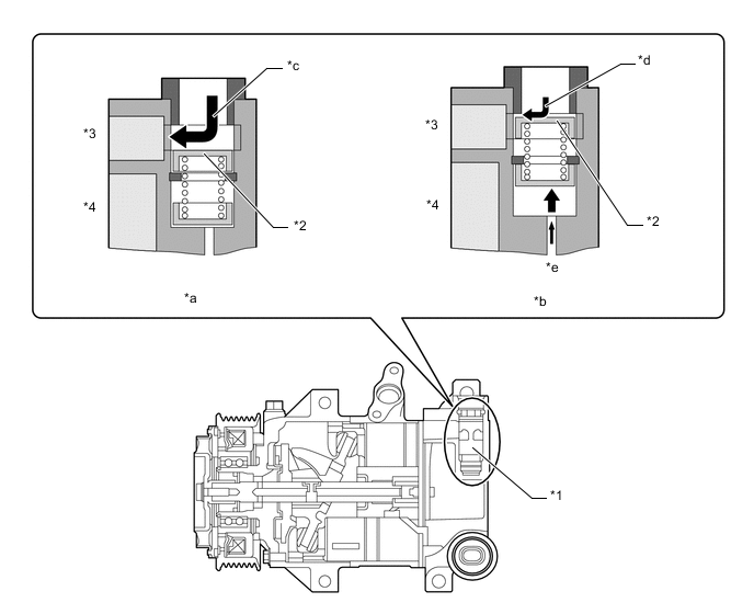
*1 Variable Suction Side Throttle *2 Spool Valve *3 Suction Chamber *4 Discharge Chamber *a With Maximum Volume of Refrigerant *b With Controlled Volume of Refrigerant *c Refrigerant Flow: Large *d Refrigerant Flow: Small *e Pressure from Swash Plate Chamber - -
-
-