INTAKE MANIFOLD INSTALLATION
PROCEDURE
INSTALL NO. 1 INTAKE MANIFOLD TO HEAD GASKET
Install a new No. 1 intake manifold to head gasket to the intake manifold.
TEMPORARILY INSTALL INTAKE MANIFOLD
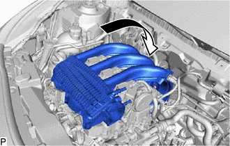
Temporarily install the intake manifold as shown in the illustration.
INSTALL FUEL DELIVERY PIPE
Install the fuel delivery pipe with the 2 bolts.
8.0 N*m
82 kgf*cm
71 in.*lbf
Connect the 3 fuel injector assembly connectors.
-
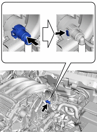
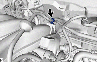
Connect the fuel tube sub-assembly as shown in the illustration.
-
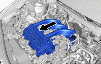
Slide the intake manifold as shown in the illustration.
INSTALL INTAKE MANIFOLD
Install the intake manifold with the 6 bolts.
8.0 N*m
82 kgf*cm
71 in.*lbf
-
Engage the wire harness clamp.
INSTALL BLOW BY HEATER (VENTILATION NO. 1 CONNECTOR) (w/ HEATER)
Install the blow by heater(ventilation No. 1 connector) with the bolt.
8.0 N*m
82 kgf*cm
71 in.*lbf
Engage the 2 clamps.
Connect the blow by heater(ventilation No. 1 connector) connector.
INSTALL BLOW BY HEATER (VENTILATION NO. 1 CONNECTOR) (w/o HEATER)
Install the blow by heater(ventilation No. 1 connector) with the bolt.
8.0 N*m
82 kgf*cm
71 in.*lbf
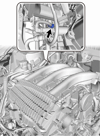
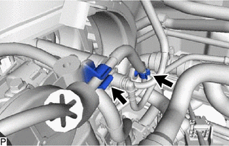
CONNECT VACUUM HOSE ASSEMBLY
-
Engage the clamp.
Connect the vacuum hose assembly to the intake manifold.
-
INSTALL NO. 1 VACUUM SWITCHING VALVE ASSEMBLY (PURGE VSV)
Install the bolt and bracket.
8.0 N*m
82 kgf*cm
71 in.*lbf
Install the No. 1 vacuum switching valve assembly (purge VSV) and bracket.
Connect the No. 1 vacuum switching valve assembly (purge VSV) connector.
INSTALL NO. 2 VACUUM PIPE
Connect the No. 2 vacuum pipe to the No. 1 vacuum switching valve assembly (purge VSV).
Install the No. 2 vacuum pipe.
INSTALL NO. 1 VACUUM PIPE
Connect the No. 1 vacuum pipe to the No. 1 vacuum switching valve assembly (purge VSV).
-
Engage the 2 clamps.
Connect the No. 1 vacuum pipe to the intake manifold.
INSTALL NOISE FILTER
Engage the clamp to install the noise filter.
Connect the noise filter connector.
INSTALL VACUUM SENSOR ASSEMBLY
INSTALL IGNITION COIL ASSEMBLY
INSTALL THROTTLE W/MOTOR BODY ASSEMBLY
INSTALL OUTER COWL TOP PANEL
for LHD:Click here
for RHD:Click here
INSTALL FRONT AIR SHUTTER SEAL RH
for LHD:Click here
for RHD:Click here
INSTALL FRONT NO. 1 VENTILATOR SEAL
for LHD:Click here
for RHD:Click here
INSTALL FRONT WIPER MOTOR AND LINK ASSEMBLY
CONNECT CABLE TO NEGATIVE BATTERY TERMINAL
Note:When disconnecting the cable, some systems need to be initialized after the cable is reconnected.
INSPECT FOR FUEL LEAK