FRONT POWER SEAT CONTROL SYSTEM(w/ Memory) Power Seat Power Easy Access System Function does not Operate
DESCRIPTION
-
The driver side power seat slides backward when either of the following conditions is met:
-
The driver seat belt is unfastened with the engine switch off and the shift lever in P.
-
The engine switch is turned from on (IG) or on (ACC) to off with the shift lever in P and the driver seat belt unfastened.
-
The driver side power seat slides forward when either of the following conditions is met:
-
The driver seat belt is fastened with the engine switch on (IG) or on (ACC) and the shift lever in P or N.
-
The engine switch is turned from off to on (IG) or on (ACC) with the shift lever in P and the driver seat belt unfastened.
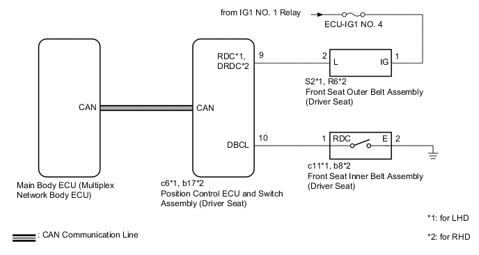
WIRING DIAGRAM
CAUTION / NOTICE / HINT
Note
-
The front power seat control system (w/ Memory) uses the CAN communication system. First, confirm that there are no malfunctions in the CAN communication system. Refer to How to Proceed with Troubleshooting.
-
Before replacing the main body ECU (multiplex network body ECU), refer to Service Bulletin.
-
The vehicle battery supplies power to the main body ECU (multiplex network body ECU) via the door control battery. Therefore, before proceeding with troubleshooting, perform an on-vehicle inspection and confirm that the main body ECU (multiplex network body ECU) power source circuit is normal.*
-
*: w/o Canister Pump Module with Door Ajar Warning Buzzer Function
-
Inspect the fuses for circuits related to this system before performing the following procedure.
PROCEDURE
-
CHECK FRONT POWER SEAT OPERATION
-
Check that each function of the power seat operates normally by using the position control ECU and switch assembly (driver seat).
Result Result Proceed to Power seat functions operate normally A All power seat functions do not operate B One or more power seat motors do not operate C
B 
GO TO OTHER DIAGNOSTIC PROCEDURE (Front Power Seat does not Operate with Front Power Seat Switch) Click here
C
GO TO OTHER DIAGNOSTIC PROCEDURE (One or more Power Seat Motors do not Operate) Click here
A 
-
-
READ VALUE USING GTS
-
Connect the GTS to the DLC3.
-
Turn the engine switch on (IG).
-
Turn the GTS on.
-
Enter the following menus: Body Electrical / Driver Seat / Data List.
-
Read the Data List according to the display on the GTS.
Body Electrical > Driver Seat > Data ListTester Display Measurement Item Range Normal Condition Diagnostic Note Driver Seat Buckle SW Driver seat belt buckle switch ON or OFF ON: Driver seat belt fastened
OFF: Driver seat belt unfastened
-
Body Electrical > Driver Seat > Data ListTester Display Driver Seat Buckle SW OK On the GTS screen, ON or OFF is displayed accordingly. Result Proceed to OK NG
NG 
INSPECT FRONT SEAT INNER BELT ASSEMBLY (DRIVER SEAT) Click here
OK
-
-
CHECK HARNESS AND CONNECTOR (FRONT SEAT OUTER BELT ASSEMBLY (DRIVER SEAT) - IG POWER SUPPLY)
-
Disconnect the S2*1 or R6*2 front seat outer belt assembly (driver seat) connector.
-
*1: for LHD
-
*2: for RHD
-
-
Measure the voltage according to the value(s) in the table below.
Standard Voltage for LHD Tester Connection Condition Specified Condition S2-1 (IG) - Body ground Engine switch on (IG) 11 to 14 V S2-1 (IG) - Body ground Engine switch off Below 1 V for RHD Tester Connection Condition Specified Condition R6-1 (IG) - Body ground Engine switch on (IG) 11 to 14 V R6-1 (IG) - Body ground Engine switch off Below 1 V Result Proceed to OK NG
NG
REPAIR OR REPLACE HARNESS OR CONNECTOR
OK
-
-
CHECK HARNESS AND CONNECTOR (FRONT SEAT OUTER BELT ASSEMBLY (DRIVER SEAT) - POSITION CONTROL ECU AND SWITCH ASSEMBLY (DRIVER SEAT))
-
Disconnect the c6*1 or b17*2 position control ECU and switch assembly (driver seat) connector.
-
*1: for LHD
-
*2: for RHD
-
-
Measure the resistance according to the value(s) in the table below.
Standard Resistance for LHD Tester Connection Condition Specified Condition S2-2 (L) - c6-9 (RDC) Always Below 1 Ω S2-2 (L) or c6-9 (RDC) - Body ground Always 10 kΩ or higher for RHD Tester Connection Condition Specified Condition R6-2 (L) - b17-9 (DRDC) Always Below 1 Ω R6-2 (L) or b17-9 (DRDC) - Body ground Always 10 kΩ or higher Result Proceed to OK NG
NG
REPAIR OR REPLACE HARNESS OR CONNECTOR
OK
-
-
CHECK SEAT BELT TENSION REDUCER SYSTEM
-
Check the seat belt tension reducer system.
OK Seat belt tension reducer system is normal. Result Proceed to OK NG
NG
REPLACE FRONT SEAT OUTER BELT ASSEMBLY (DRIVER SEAT) Click here
OK
-
-
REPLACE POSITION CONTROL ECU AND SWITCH ASSEMBLY (DRIVER SEAT)
-
Replace the position control ECU and switch assembly (driver seat) with a new or known good one.
Result Proceed to NEXT
NEXT
-
-
CHECK POWER SEAT POWER EASY ACCESS SYSTEM
-
Check the power seat power easy access system.
OK Power seat power easy access system is normal. Result Proceed to OK NG
OK
END (POSITION CONTROL ECU AND SWITCH ASSEMBLY (DRIVER SEAT) WAS DEFECTIVE)
NG
REPLACE MAIN BODY ECU (MULTIPLEX NETWORK BODY ECU) Click here
-
-
INSPECT FRONT SEAT INNER BELT ASSEMBLY (DRIVER SEAT)
-
Remove the front seat inner belt assembly (driver seat).
-
Inspect the front seat inner belt assembly (driver seat).
Result Proceed to OK NG
NG
REPLACE FRONT SEAT INNER BELT ASSEMBLY (DRIVER SEAT) Click here
OK
-
-
CHECK HARNESS AND CONNECTOR (POSITION CONTROL ECU AND SWITCH ASSEMBLY (DRIVER SEAT) - FRONT SEAT INNER BELT ASSEMBLY (DRIVER SEAT))
-
Disconnect the c6*1 or b17*2 position control ECU and switch assembly (driver seat) connector.
-
*1: for LHD
-
*2: for RHD
-
-
Measure the resistance according to the value(s) in the table below.
Standard Resistance for LHD Tester Connection Condition Specified Condition c6-10 (DBCL) - c11-1 (RDC) Always Below 1 Ω c6-10 (DBCL) or c11-1 (RDC) - Body ground Always 10 kΩ or higher for RHD Tester Connection Condition Specified Condition b17-10 (DBCL) - b8-1 (RDC) Always Below 1 Ω b17-10 (DBCL) or b8-1 (RDC) - Body ground Always 10 kΩ or higher Result Proceed to OK NG
OK
REPLACE POSITION CONTROL ECU AND SWITCH ASSEMBLY (DRIVER SEAT) Click here
NG
REPAIR OR REPLACE HARNESS OR CONNECTOR
-