MANUAL TRANSAXLE ASSEMBLY REMOVAL
PROCEDURE
PRECAUTION
Note:After turning the ignition switch off, waiting time may be required before disconnecting the cable from the negative (-) battery terminal. Therefore, make sure to read the disconnecting the cable from the negative (-) battery terminal notices before proceeding with work.
DISCONNECT CABLE FROM NEGATIVE BATTERY TERMINAL
Note:When disconnecting the cable, some systems need to be initialized after the cable is reconnected.
REMOVE BATTERY
REMOVE AIR CLEANER CASE SUB-ASSEMBLY
DISCONNECT TRANSMISSION CONTROL CABLE ASSEMBLY
SEPARATE NO. 1 ENGINE ROOM RELAY BLOCK
-
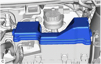
Remove the No. 1 engine room relay block cover.
-
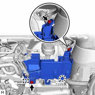
Remove the 2 bolts.
Disengage the wire harness clamp and disconnect the wire harness from the battery clamp sub-assembly.
Disengage the claw and separate the No. 1 engine room relay block from the battery clamp sub-assembly.
-
REMOVE BATTERY CLAMP SUB-ASSEMBLY
Remove the 3 bolts.
-
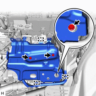
Disengage the 3 wire harness clamps to disconnect the wire harness from the battery clamp sub-assembly.
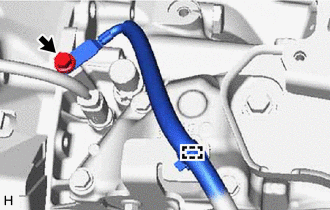
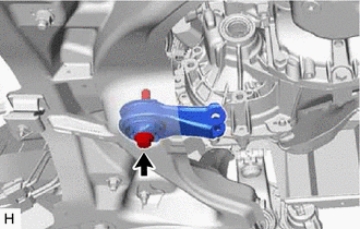
REMOVE SHIFT AND SELECT LEVER BUSH
-
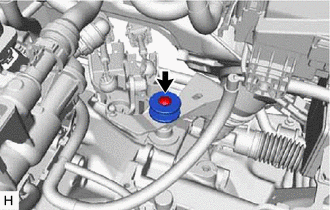
Remove the bolt and shift and select lever bush from the manual transaxle assembly.
-
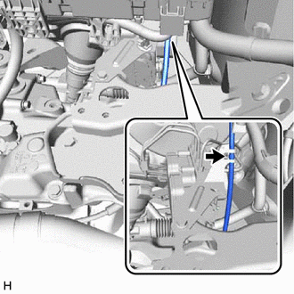
DISCONNECT WIRE HARNESS
-
Disconnect the back-up light switch assembly connector.
-
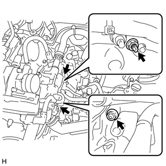
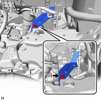
Remove the 2 nuts and wire harness bracket from the manual transaxle assembly.
-
Remove the bolt and No. 3 engine wire from the manual transaxle assembly.
Disengage the wire harness clamp to disconnect the No. 3 engine wire from the clutch cable bracket.
-
DISCONNECT CLUTCH RELEASE CABLE ASSEMBLY
-
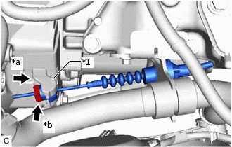
*1
Clutch Release Fork Sub-assembly
*a
Push
*b
Turn
While pushing the clutch release fork sub-assembly, turn and loosen the clutch release cable end clamp.
-
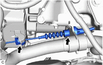
Disconnect the clutch release cable assembly from the manual transaxle assembly.
-
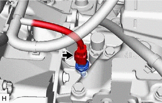
DISCONNECT NO. 2 RADIATOR HOSE
-
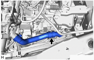
Disconnect the No. 2 radiator hose from the clutch cable bracket.
-
REMOVE CLUTCH CABLE BRACKET
-
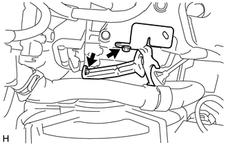
Remove the 2 bolts and clutch cable bracket from the manual transaxle assembly.
-
DRAIN MANUAL TRANSAXLE OIL
REMOVE FRONT EXHAUST PIPE ASSEMBLY
Remove the nut from the exhaust pipe support.
-
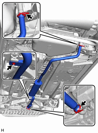
Remove the 2 nuts, 2 spacers and 2 clamps from the front exhaust pipe assembly.
Remove the front exhaust pipe assembly from the exhaust manifold, exhaust pipe support and tail exhaust pipe assembly.
REMOVE FRONT DRIVE SHAFT ASSEMBLY
REMOVE CONTROL CABLE BRACKET
-
Remove the 2 bolts and control cable bracket from the manual transmission assembly.
-
REMOVE STARTER ASSEMBLY
-
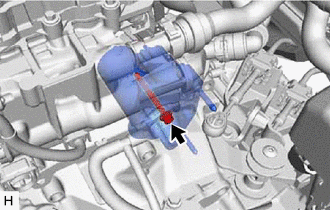
Using a 6 mm hexagon wrench, remove the bolt.
-
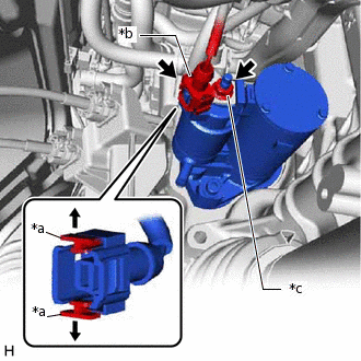
*a
Tab
*b
Starter Assembly Connector
*c
Nut
Pull out the tabs as shown in the illustration and disconnect the starter assembly connector.
Note:To prevent damage to the connector, do not pull out the tabs excessively.
Remove the nut and disconnect terminal 30.
-
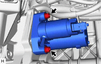
Using a 6 mm hexagon wrench, remove the 2 bolts and starter assembly.
-
DISCONNECT FRONT FENDER LINER LH
-
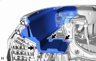

Bolt

Screw
Remove the 2 screws and 3 bolts to disconnect the front fender liner LH.
-
SUPPORT ENGINE ASSEMBLY
-
Remove the 3 bolts from the engine assembly.
-
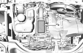
*a
Attachment Installation Position
Support the engine assembly with an engine lifter.
-
SUPPORT MANUAL TRANSAXLE ASSEMBLY
Support the manual transaxle assembly with a transmission jack.
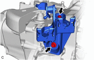
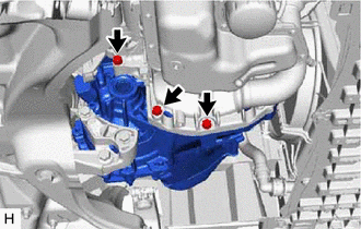
REMOVE ENGINE MOUNTING CONTROL BRACKET
-
Remove the 3 bolts and engine mounting control bracket from the manual transaxle assembly.
-
REMOVE ENGINE MOVING CONTROL ROD
-
Remove the bolt and engine moving control rod from the front suspension crossmember sub-assembly.
-
REMOVE ENGINE MOUNTING INSULATOR LH
-
Disconnect the clutch release cable assembly from the clutch release cable clamp.
-
Remove the bolt and clutch release cable clamp from the engine mounting insulator LH.
-
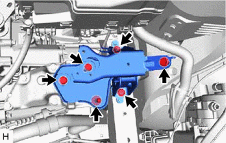
Remove the 6 bolts and engine mounting insulator LH from the vehicle body and engine mounting bracket LH.
-
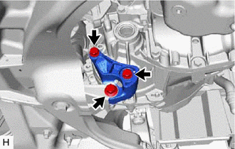
REMOVE ENGINE MOUNTING BRACKET LH
-
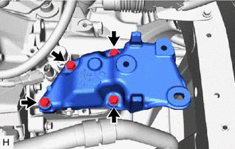
Remove the 4 bolts and engine mounting bracket LH from the manual transaxle assembly.
-
REMOVE MANUAL TRANSAXLE ASSEMBLY
-
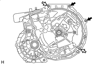
Bolt
Nut
Remove the 2 bolts and 2 nuts.
Remove the manual transaxle assembly as shown in the illustration.
CAUTION:When rotating and removing the manual transaxle assembly, do not allow it to contact any surrounding parts or drop from the transmission jack.
Note:To prevent damage to the 2 knock pins, do not pry between the manual transaxle assembly and engine assembly.
Do not apply excessive force to the manual transaxle assembly as this will break the input shaft.
Be careful not to damage the No. 2 radiator hose and fan shroud assembly when removing the manual transaxle assembly.
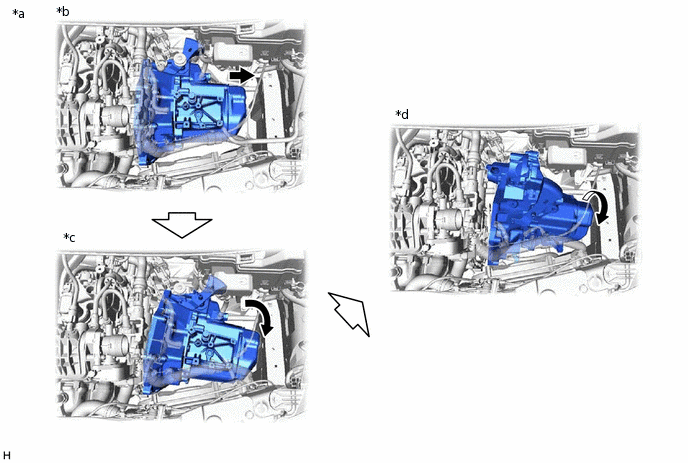
*a
Top View
*b
Pull the manual transaxle assembly toward the outside of the vehicle.
*c
Move the manual transaxle assembly toward the front of the vehicle.
*d
Rotate the manual transaxle assembly.
Remove the manual transaxle assembly.
-