INTAKE MANIFOLD REMOVAL
PROCEDURE
DISCHARGE FUEL SYSTEM PRESSURE
DISCONNECT CABLE FROM NEGATIVE BATTERY TERMINAL
Note:When disconnecting the cable, some systems need to be initialized after the cable is reconnected.
REMOVE FRONT WIPER MOTOR AND LINK ASSEMBLY
REMOVE FRONT NO. 1 VENTILATOR SEAL
for LHD:Click here
for RHD:Click here
REMOVE FRONT AIR SHUTTER SEAL RH
for LHD:Click here
for RHD:Click here
REMOVE OUTER COWL TOP PANEL
for LHD:Click here
for RHD:Click here
REMOVE THROTTLE W/MOTOR BODY ASSEMBLY
REMOVE IGNITION COIL ASSEMBLY
REMOVE VACUUM SENSOR ASSEMBLY
REMOVE NOISE FILTER
-
Disconnect the noise filter connector.
-
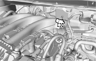
Disengage the clamp and remove the noise filter.
-
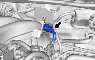
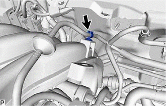
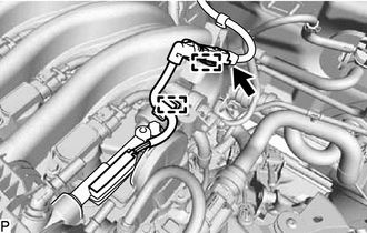
REMOVE NO. 1 VACUUM PIPE
Remove the No. 1 vacuum pipe from the intake manifold.
-
Disengage the 2 clamps.
-
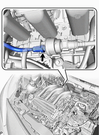
Remove the No. 1 vacuum pipe from the No. 1 vacuum switching valve assembly (purge VSV).
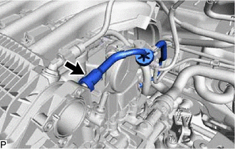
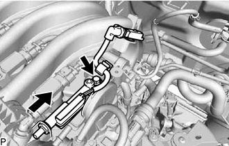
REMOVE NO. 2 VACUUM PIPE
-
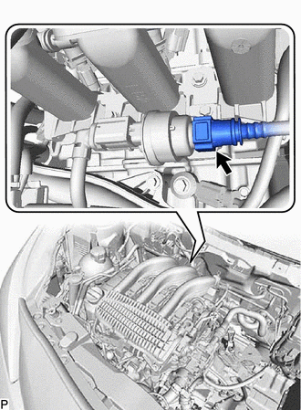
Disconnect the No. 2 vacuum pipe from the No. 1 vacuum switching valve assembly (purge VSV).
-
Remove the No. 2 vacuum pipe.
-
REMOVE NO. 1 VACUUM SWITCHING VALVE ASSEMBLY (PURGE VSV)
-
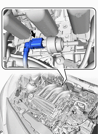
Disconnect the No. 1 vacuum switching valve assembly (purge VSV) connector.
-
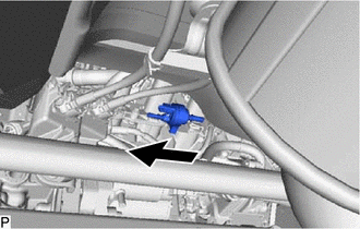
Remove the No. 1 vacuum switching valve assembly (purge VSV) and bracket.
-
Remove the bolt and bracket.
-
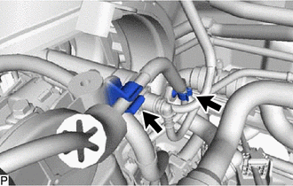
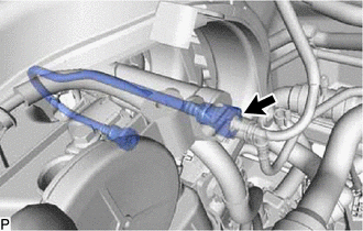
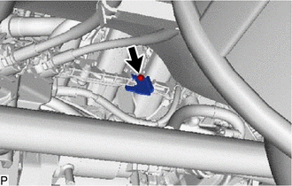
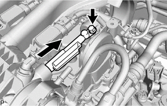
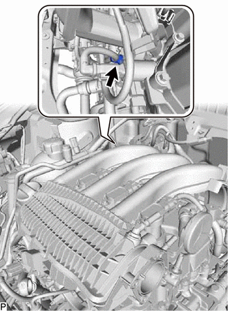
DISCONNECT VACUUM HOSE ASSEMBLY
-
Disconnect the vacuum hose assembly from the intake manifold.
-
Disengage the clamp.
-
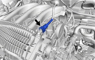
REMOVE BLOW BY HEATER (VENTILATION NO. 1 CONNECTOR) (w/ HEATER)
-
Disconnect the blow by heater(ventilation No. 1 connector) connector.
Disengage the 2 clamps.
-
Remove the bolt and blow by heater(ventilation No. 1 connector).
-
REMOVE BLOW BY HEATER (VENTILATION NO. 1 CONNECTOR) (w/o HEATER)
-
Remove the bolt and blow by heater(ventilation No. 1 connector).
-
SEPARATE INTAKE MANIFOLD
-
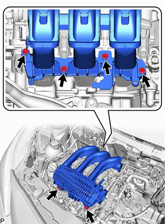
Remove the 6 bolts.
-
Disengage the wire harness clamp to separate the intake manifold.
-
REMOVE FUEL DELIVERY PIPE
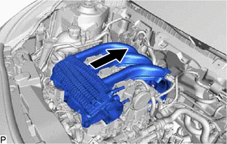
Slide the intake manifold as shown in the illustration.
-
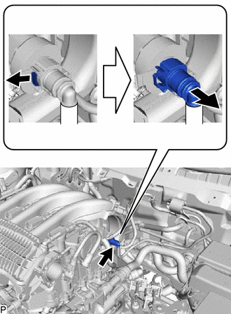
Disconnect the fuel tube sub-assembly as shown in the illustration.
-
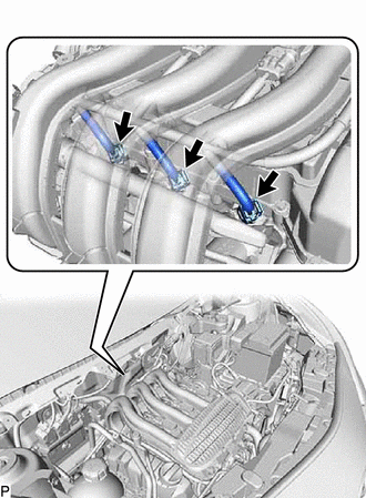
Disconnect the 3 fuel injector assembly connectors.
-
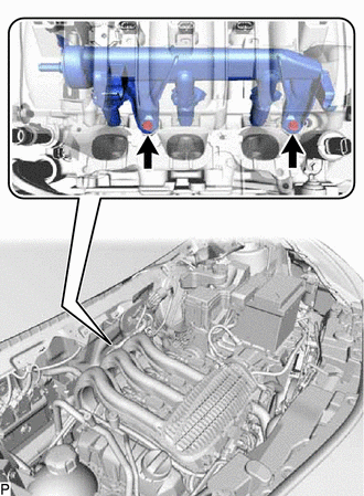
Remove the 2 bolts and fuel delivery pipe.
REMOVE INTAKE MANIFOLD
-
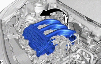
Remove the intake manifold as shown in the illustration.
-
REMOVE NO. 1 INTAKE MANIFOLD TO HEAD GASKET
-
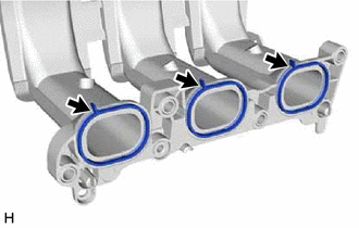
Remove the No. 1 intake manifold to head gasket from the intake manifold.
-