EXHAUST MANIFOLD W/ TURBOCHARGER REASSEMBLY
PROCEDURE
-
INSTALL TURBOCHARGER GASKET
-
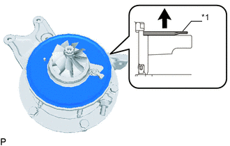
*1 Turbocharger Gasket 
Upper Install a new turbocharger gasket to the compressor with bearing housing sub-assembly.
Tech Tips
-
Install the turbocharger gasket facing the direction shown in the illustration.
-
Make sure to install the turbocharger gasket so that the white coating faces downwards.
-
-
-
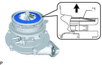
INSTALL SEAL RING
-
Install a new seal ring to the compressor with bearing housing sub-assembly.
Note
Do not reuse the seal ring.
-
-
INSTALL TURBOCHARGER NOZZLE VANE PLATE SUB-ASSEMBLY
-
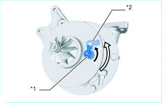
*1 No. 2 Turbocharger Nozzle Vane Arm *2 No. 2 Turbocharger Nozzle Vane Control Link No. 2 Turbocharger Nozzle Vane Arm Fully Open 
No. 2 Turbocharger Nozzle Vane Control Link Fully Open Align the No. 2 turbocharger nozzle vane arm as shown in the illustration.
-
Install the turbocharger nozzle vane plate sub-assembly to the compressor with bearing housing sub-assembly.
Note
-
When installing the turbocharger nozzle vane plate sub-assembly, align the installation positions on the pin side and No. 2 turbocharger nozzle vane arm side.
-
Do not remove the No. 2 turbocharger nozzle vane plate and turbocharger nozzle vane spacer.
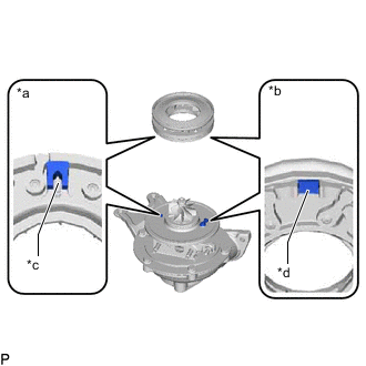
*a Bearing Housing Pin Side *b No. 2 Turbocharger Nozzle Vane Arm Side *c Installation Positions Pin Side *d Installation Positions No. 2 Turbocharger Nozzle Vane Arm Side -
-
*1 Turbocharger Nozzle Vane Support Plate Upper Install the turbocharger nozzle vane support plate to the turbocharger nozzle vane plate sub-assembly.
Note
If the turbocharger nozzle vane support plate is bent or twisted, replace it.
Tech Tips
Install the turbocharger nozzle vane support plate facing the direction shown in the illustration.
-
-
INSTALL TURBINE HOUSING
-
Temporarily install the turbine housing to the compressor with bearing housing sub-assembly with 5 new bolts and 5 new spacers.
Tech Tips
Align the matchmark as shown in the illustration to install the part.
*a Matchmark -
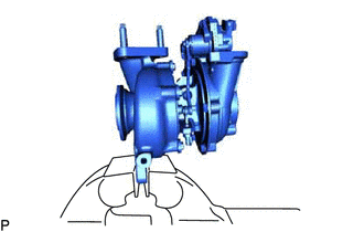
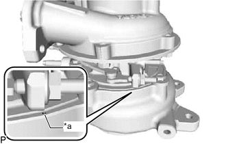
Secure the flange of the turbine housing sub-assembly of the turbocharger sub-assembly in a vise between aluminum plates.
Note
Do not tighten the vise more than necessary, as doing so will damage the flange of the turbine housing sub-assembly.
-
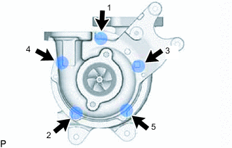
Using a 10 mm union nut wrench, tighten the 5 bolts in the order shown in the illustration.
- Torque:
- Specified tightening torque
- 15 N*m { 153 kgf*cm, 11 ft.*lbf }
Note
Move the turbocharger vane control link sub-assembly and check that the turbocharger nozzle vane plate sub-assembly smoothly operates.
Tech Tips
-
Calculate the torque wrench reading when changing the fulcrum length of the torque wrench.
-
When using a union nut wrench (fulcrum length of 22 mm (0.866 in.)) + torque wrench (fulcrum length of 180 mm (7.09 in.)): 13.4 N*m (137 kgf*cm, 10 ft.*lbf)
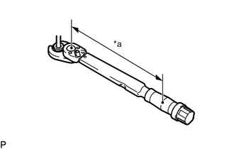
*a Torque Wrench Fulcrum Length
-
-
INSTALL TURBOCHARGER NOZZLE VANE CONTROL ACTUATOR
-
Install the turbocharger nozzle vane control actuator with the 3 bolts.
- Torque:
- 12.3 N*m { 125 kgf*cm, 9 ft.*lbf }
-
-
INSTALL TURBOCHARGER VANE CONTROL ROD SUB-ASSEMBLY
-
Install the turbocharger vane control rod sub-assembly.
-
Install 2 new E-washers to the variable nozzle vane motor assembly and turbocharger vane control link sub-assembly.
Note
Do not reuse the E-washer.
-