CHARGING SYSTEM, Diagnostic DTC:P162B
| DTC Code | DTC Name |
|---|---|
| P162B | Lost Communication with Battery Monitor Module |
DESCRIPTION
The ECM and battery state sensor assembly each detect reception malfunctions. A battery state sensor assembly reception malfunction detected by the battery state sensor assembly is sent to the ECM via LIN communication. If there is a malfunction in either the ECM or battery state sensor assembly, the ECM determines that there is a LIN communication malfunction and outputs a DTC.
DTC No. |
Detection Item |
DTC Detection Condition |
Trouble Area |
Warning Indicate |
Memory |
|---|---|---|---|---|---|
P162B |
Lost Communication with Battery Monitor Module |
Diagnosis condition: Ignition switch to ON When the ECM cannot receive LIN communication, the battery state sensor assembly cannot receive LIN communication for approximately 33 seconds or more. Other: 1 trip |
|
Not displayed |
DTC stored |
WIRING DIAGRAM
Refer to DTC P161A (Lost Communication with Alternator).
CAUTION / NOTICE / HINT
Inspect the fuses for circuits related to this system before performing the following inspection procedure.
PROCEDURE
CHECK BATTERY STATE SENSOR ASSEMBLY INSTALLATION
Check the installation condition of the battery state sensor assembly.
Result
Proceed to
OK
NG
CHECK CHARGING SYSTEM
Check the charging system.
Result
Result
OK
NG
NG REPAIR OR REPLACE CHARGING SYSTEM
CHECK HARNESS AND CONNECTOR (ECM - BATTERY STATE SENSOR ASSEMBLY)
Disconnect the B93 ECM connector.
Disconnect the A75 battery state sensor assembly connector.
Disconnect the B90 generator assembly connector.
Measure the resistance according to the value(s) in the table below.
Standard Resistance
Tester Connection
Condition
Specified Condition
B93-61 (LIN) - A75-2 (LIN)
Always
Below 1 Ω
B93-61 (LIN) or A75-2 (LIN) - Body ground
Ignition switch off
(while LIN communication is stopped)
10 kΩ or higher
Result
Proceed to
OK
NG
NG REPAIR OR REPLACE HARNESS OR CONNECTOR
CHECK HARNESS AND CONNECTOR (POWER SOURCE CIRCUIT)
-
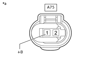
*a
Front view of wire harness connector
(to Battery State Sensor Assembly)
Disconnect the A75 battery state sensor assembly connector.
Measure the voltage according to the value(s) in the table below.
Standard Voltage
Tester Connection
Condition
Specified Condition
A75-1 (+B) - Body ground
Always
11 to 14 V
Result
Result
OK
NG
NG REPAIR OR REPLACE HARNESS OR CONNECTOR
-
READ OUTPUT DTC
Connect the GTS to the DLC3.
Turn the ignition switch to ON.
Turn the GTS on.
Clear the DTCs.
Powertrain > Engine and ECT > Clear DTCs
Turn the ignition switch off and wait at least 30 seconds.
Start the engine and wait 17 minutes or more.
Enter the following menus: Powertrain / Engine and ECT / Trouble Codes.
Read the DTCs.
Powertrain > Engine and ECT > Trouble Codes
Result
Result
Proceed to
DTC P162B is output
A
P161A and P162B are output
B
No DTC is output
C