ECD SYSTEM, Diagnostic DTC:P2454 and P2455
| DTC Code | DTC Name |
|---|---|
| P2454 | Diesel Particulate Filter Pressure Sensor "A" Circuit Low |
| P2455 | Diesel Particulate Filter Pressure Sensor "A" Circuit High |
DESCRIPTION
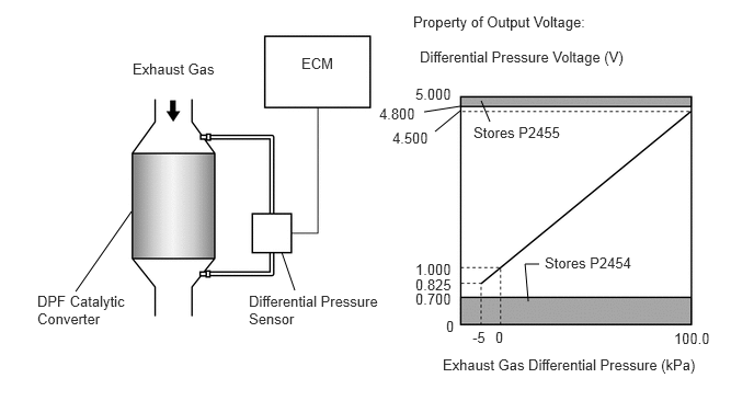
The two sensing chambers of the differential pressure sensor are mounted to monitor the pressure before and after the DPF catalytic converter.
The ECM compares the exhaust gas pressure before and after the DPF catalytic converter by monitoring the pressure using the upstream and downstream sensing chambers of the differential pressure sensor. If the difference between the pressure before and after the DPF catalytic converter exceeds a predetermined level, the ECM judges that the catalytic converter is clogged with particulate matter (PM).
When the ECM judges that a partially clogged condition exists, the ECM begins to perform PM forced regeneration.
When the output voltage of the sensor deviates from the normal operating range, the ECM interprets this as a malfunction of the sensor circuit, and sets DTC P2454 or P2455, and illuminates the MIL.
DTC No. |
Detection Item |
DTC Detection Condition |
Trouble Area |
MIL |
Memory |
|---|---|---|---|---|---|
P2454 |
Diesel Particulate Filter Pressure Sensor "A" Circuit Low |
Differential pressure sensor output voltage is 0.7 V or less for 0.6 seconds. (3 trip detection logic) |
|
Comes on |
DTC stored |
P2455 |
Diesel Particulate Filter Pressure Sensor "A" Circuit High |
Differential pressure sensor output voltage is 4.8 V or more 0.6 seconds. (3 trip detection logic) |
|
Comes on |
DTC stored |
DTC No. |
Data List |
|---|---|
P2454 P2455 |
Adaptation Value of Differential Pressure at Particle Filter |
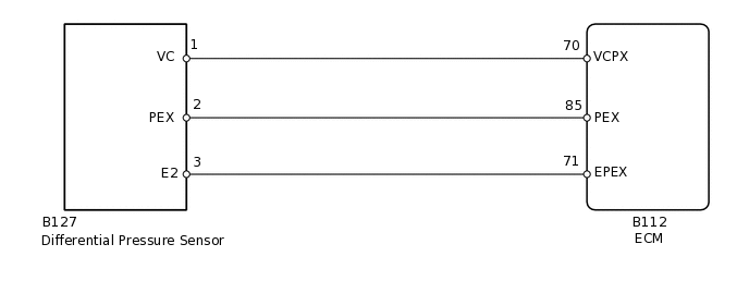
WIRING DIAGRAM
CAUTION / NOTICE / HINT
When replacing the ECM, the ECM needs registration and initialization.
After replacing the differential pressure sensor, the ECM needs initialization.
When the ECM must be replaced, before replacing the ECM, perform the "Learning Values Save" function using the GTS. Then after installing the new ECM, perform all of the initialization/registrations for the "Learning Values Write" function by following the instructions shown on the GTS display.
Read freeze frame data using the GTS. Freeze frame data records the engine condition when malfunctions are detected. When troubleshooting, freeze frame data can help determine if the vehicle was moving or stationary, if the engine was warmed up or not, and other data from the time the malfunction occurred.
PROCEDURE
READ VALUE USING GTS (ADAPTATION VALUE OF DIFFERENTIAL PRESSURE AT PARTICLE FILTER)
Connect the GTS to the DLC3.
Turn the ignition switch to ON and turn the GTS on.
Enter the following menus: Powertrain / Engine and ECT / Data List / Adaptation Value of Differential Pressure at Particle Filter.
Powertrain > Engine and ECT > Data List
Tester Display
Adaptation Value of Differential Pressure at Particle Filter
Start the engine.
Read the values while revving the engine at high speeds.
OK
The values in the Data List change according to changes in the engine speed.
Result
Proceed to
OK
NG
OK CONFIRM WHETHER MALFUNCTION HAS BEEN SUCCESSFULLY REPAIREDClick here
CHECK HARNESS AND CONNECTOR (DIFFERENTIAL PRESSURE SENSOR - ECM)
Disconnect the differential pressure sensor connector.
Disconnect the ECM connector.
Measure the resistance according to the value(s) in the table below.
Standard Resistance
Tester Connection
Condition
Specified Condition
B127-1 (VC) - B112-70 (VCPX)
Always
Below 1 Ω
B127-2 (PEX) - B112-85 (PEX)
Always
Below 1 Ω
B127-3 (E2) - B112-71 (EPEX)
Always
Below 1 Ω
B127-1 (VC) or B112-70 (VCPX) - Body ground
Always
10 kΩ or higher
B127-2 (PEX) or B112-85 (PEX) - Body ground
Always
10 kΩ or higher
B127-3 (E2) or B112-71 (EPEX) - Body ground
Always
10 kΩ or higher
Result
Proceed to
OK
NG
NG REPAIR OR REPLACE HARNESS OR CONNECTORClick here
CHECK HARNESS AND CONNECTOR (VC VOLTAGE)
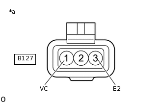
*a
Front view of wire harness connector
(to Differential Pressure Sensor)
Disconnect the differential pressure sensor connector.
Turn the ignition switch to ON.
Measure the voltage according to the value(s) in the table below.
Standard Voltage
Tester Connection
Switch Condition
Specified Condition
B127-1 (VC) - B127-3 (E2)
Ignition switch ON
4.5 to 5.5 V
Result
Proceed to
OK
NG
NG REPLACE ECMClick here
REPLACE DIFFERENTIAL PRESSURE SENSOR
Replace the differential pressure sensor.
Perform differential pressure learning value reset.
Result
Proceed to
NEXT
CHECK WHETHER DTC OUTPUT RECURS (DTC P2454 OR P2455)
Connect the GTS to the DLC3.
Turn the ignition switch to ON and turn the GTS on
Clear the DTCs.
Powertrain > Engine and ECT > Clear DTCs
Turn the ignition switch off and wait for 60 seconds or more [A].
Perform road test [B].
Repeat [A] and [B] for the number of trips detected.
Enter the following menus: Powertrain / Engine and ECT / Trouble Codes.
Powertrain > Engine and ECT > Trouble Codes
Read the DTCs.
Result
Result
Proceed to
No DTC output
A
DTC P2454 or P2455
B
A END
B REPLACE ECMClick here
REPLACE ECM
Replace the ECM.
Result
Proceed to
NEXT
NEXT CONFIRM WHETHER MALFUNCTION HAS BEEN SUCCESSFULLY REPAIREDClick here
REPAIR OR REPLACE HARNESS OR CONNECTOR
Repair or replace the harness or connector.
Result
Proceed to
NEXT
CONFIRM WHETHER MALFUNCTION HAS BEEN SUCCESSFULLY REPAIRED
Connect the GTS to the DLC3.
Turn the ignition switch to ON and turn the GTS on.
Clear the DTCs.
Powertrain > Engine and ECT > Clear DTCs
Turn the ignition switch off and wait for 60 seconds or more [A].
Perform road test [B].
Repeat [A] and [B] for the number of trips detected.
Enter the following menus: Powertrain / Engine and ECT / Trouble Codes.
Powertrain > Engine and ECT > Trouble Codes
Confirm that the DTC is not output again.
Result
Proceed to
NEXT
NEXT END