ВПУСКНОЙ КОЛЛЕКТОР СНЯТИЕ
CAUTION / NOTICE / HINT
The necessary procedures (adjustment, calibration, initialization, or registration) that must be performed after parts are removed, installed, or replaced during the intake manifold removal/installation are shown below.
| Replacement Part or Procedure | Necessary Procedures | Effects/Inoperative when not Performed | Link |
|---|---|---|---|
| Battery terminal is disconnected/reconnected | Drive the vehicle until stop and start control is permitted (approximately 5 to 60 minutes) | Stop and start system | |
| Memorize steering angle neutral point | Panoramic view monitor system | ||
| Initialize back door lock | Power door lock control system | ||
| Initialize servo motor | Air conditioning system | ||
| Reset slide door close position | Power slide door system | ||
| Reset back door close position | Power back door system | ||
| Throttle body with motor assembly | Inspection After Repair |
|
|
| Cleaning the deposits from the throttle body with motor assembly |
PROCEDURE
-
PRECAUTION
Note
After turning the engine switch off, waiting time may be required before disconnecting the cable from the negative (-) battery terminal. Therefore, make sure to read the disconnecting the cable from the negative (-) battery terminal notices before proceeding with work.
-
DISCHARGE FUEL SYSTEM PRESSURE
-
DISCONNECT CABLE FROM NEGATIVE BATTERY TERMINAL
Note
When disconnecting the cable, some systems need to be initialized after the cable is reconnected.
-
REMOVE WINDSHIELD WIPER MOTOR AND LINK ASSEMBLY
-
SEPARATE BRAKE MASTER CYLINDER RESERVOIR ASSEMBLY
-
REMOVE NO. 1 HEATER AIR DUCT SPLASH SHIELD SEAL
-
REMOVE NO. 2 HEATER AIR DUCT SPLASH SHIELD SEAL
-
REMOVE OUTER COWL TOP PANEL SUB-ASSEMBLY
-
REMOVE THROTTLE BODY WITH MOTOR ASSEMBLY
-
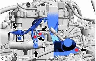
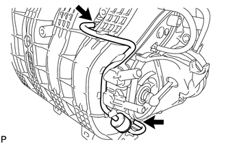
REMOVE VACUUM SWITCHING VALVE ASSEMBLY (for ACIS)
-
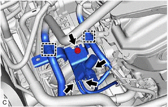
Disconnect the union to check valve hose from the vacuum hose clamp.
-
Disengage the wire harness clamp.
-
Disconnect the 2 vacuum hoses.
-
Disconnect the vacuum switching valve assembly (for ACIS) connector.
-
Remove the bolt and vacuum switching valve assembly (for ACIS) from the intake manifold.
-
-
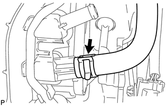
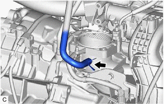
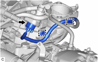
DISCONNECT NO. 2 VENTILATION HOSE
-
Slide the clip and disconnect the No. 2 ventilation hose from the intake manifold.
-
-
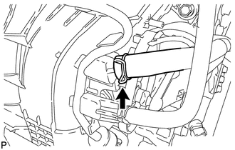
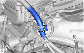
DISCONNECT UNION TO CHECK VALVE HOSE
-
Slide the clip and disconnect the union to check valve hose from the intake manifold.
-
-
DISCONNECT FUEL TUBE SUB-ASSEMBLY
-
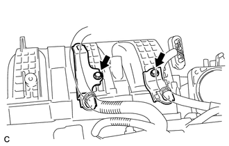
DISCONNECT ENGINE WIRE
-
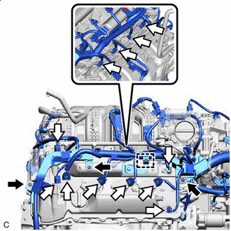

Nut 
Connector Remove the 3 nuts and disconnect the engine wire from the cylinder head cover sub-assembly.
-
Disconnect the 12 connectors and disengage the wire harness clamp.
-
Remove the 2 bolts and 2 wire harness clamp brackets from the intake manifold.
-
Remove the 2 bolts and disconnect the engine wire from the cylinder head sub-assembly.
-
Remove the bolt and disconnect the engine wire from the wire harness bracket.
-
Disconnect the 2 connectors and disengage the wire harness clamp.
-
Disengage the wire harness clamp and disconnect the engine wire.
-
-
REMOVE FUEL DELIVERY PIPE
-
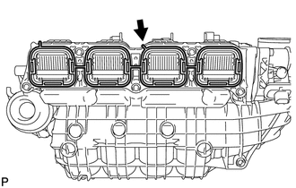
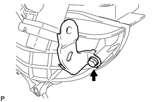
REMOVE INTAKE MANIFOLD
-
Slide the clip and disconnect the fuel vapor feed hose from the intake manifold.
-
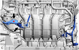
Disengage the 2 wire harness clamps.
-
Disconnect the sensor wire connector.
-
Remove the bolt and disconnect the wire harness clamp bracket from the intake manifold.
-
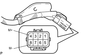
Apply positive (+) battery voltage to terminal 8 (M-) and negative (-) battery voltage to terminal 4 (M+) of the sensor wire connector to close the 4 tumble control valves (TCV).
Note
-
The 4 tumble control valves (TCV) may be damaged if they are not closed before removing the intake manifold.
-
Apply battery voltage for 1 to 3 seconds.
-
If battery voltage is applied for more than 3 seconds, the intake air control valve actuator (for TCV) may be damaged.
-
Do not allow the lead wires to contact the other terminals.
-
-
Disengage the 2 wire harness clamps.
-
Disconnect the intake air control valve actuator (for TCV) connector.
-
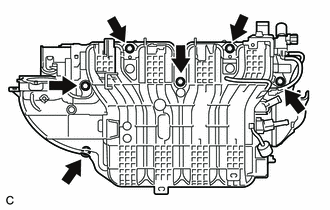
Remove the 6 bolts and intake manifold from the cylinder head sub-assembly.
Note
The 4 tumble control valves (TCV) may be damaged if they are not closed before removing the intake manifold.
Tech Tips
Connect the battery to the terminals of the intake air control valve actuator (for TCV) to operate the motor and close the 4 tumble control valves (TCV).
-
Remove the intake manifold to head gasket from the intake manifold.
-
Disconnect the 2 vacuum hoses and remove the No. 1 check valve from the intake manifold.
-
Remove the bolt and wire harness clamp bracket from the intake manifold.
-